![]()
![]()
|
|
SOLAR ENERGY |
|
|
Solar energy runs the engines of the earth. It heats its atmosphere and its lands, generates its winds, drives the water cycle, warms its oceans, grows its plants, feeds its animals, and even (over the long haul) produces its fossil fuels. This energy can be converted into heat and cold, driving force and electricity. |
SOLAR RADIATION
|
|
Solar radiation is electromagnetic radiation in the
0.28...3.0 µm wavelength range. The solar spectrum includes a small share of
ultraviolet radiation (0.28...0.38 µm) which is invisible to our eyes and
comprises about 2% of the solar spectrum, the visible light which range from
0.38 to 0.78 µm and accounts for around 49% of the spectrum and finally of
infrared radiation with long wavelength (0.78...3.0 µm), which makes up most
of the remaining 49% of the solar spectrum. |
HOW MUCH SOLAR ENERGY
STRIKES THE EARTH?
The sun generates an enormous amount of energy - approximately 1.1 x 10 E20
kilowatt-hours every second. (A kilowatt-hour is the amount of energy needed to
power a 100 watt light bulb for ten hours.) The earth's outer atmosphere
intercepts about one two-billionth of the energy generated by the sun, or about
1500 quadrillion (1.5 x 10 E18 ) kilowatt-hours per year. Because of
reflection, scattering, and absorption by gases and aerosols in the atmosphere,
however, only 47% of this, or approximately 700 quadrillion (7 x 10 E17 )
kilowatt-hours, reaches the surface of the earth.

|
|
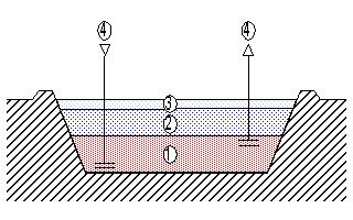
In the earth's atmosphere, solar radiation is received directly (direct radiation) and by diffusion in air, dust, water, etc., contained in the atmosphere (diffuse radiation). The sum of the two is referred to as global radiation. |
The amount of incident energy per unit area and day
depends on a number of factors, e.g.:
![]() latitude
latitude
![]() local climate
local climate
![]() season of the year
season of the year
![]() inclination of the collecting surface in the direction of the
sun.
inclination of the collecting surface in the direction of the
sun.
TIME AND SITE
The solar energy varies because of the relative motion of the sun. This
variations depend on the time of day and the season. In general, more
solar radiation is present during midday than during either the early morning
or late afternoon. At midday, the sun is positioned high in the sky and the path
of the sun's rays through the earth's atmosphere is shortened. Consequently,
less solar radiation is scattered or absorbed, and more solar radiation reaches
the earth's surface.

The amounts of solar energy arriving at the earth's surface vary over the
year, from an average of less than 0,8 kWh/m2 per day during winter in the
North of Europe to more than 4 kWh/m2 per day during summer in this region. The
difference is decreasing for the regions closer to the equator.
The availability of solar energy varies with geographical location of site
and is the highest in regions closest to the equator. Thus the average annual
global radiation impinging on a horizontal surface which amounts to approx.
1000 kWh/m2 in Central Europe, Central Asia, and Canada reach approx. 1700
kWh/m2 in the Mediterranian and to approx. 2200 kWh/m2 in most equatorial
regions in African, Oriental, and Australian desert areas. In general, seasonal
and geographical differences in irradiation are considerable (see the table
bellow) and must be taken into account for all solar energy applications.
Variations of solar irradiation
(tilt angle South 30Deg.) in Europe and Caribbean region in kWh/m2.day.
|
|
Southern Europe |
Central Europe |
North Europe |
Caribbean |
|
January |
2,6 |
1,7 |
0,8 |
5,1 |
|
February |
3,9 |
3,2 |
1,5 |
5,6 |
|
March |
4,6 |
3,6 |
2,6 |
6,0 |
|
April |
5,9 |
4,7 |
3,4 |
6,2 |
|
May |
6,3 |
5,3 |
4,2 |
6,1 |
|
June |
6,9 |
5,9 |
5,0 |
5,9 |
|
July |
7,5 |
6,0 |
4,4 |
6,0 |
|
August |
6,6 |
5,3 |
4,0 |
6,1 |
|
September |
5,5 |
4,4 |
3,3 |
5,7 |
|
October |
4,5 |
3,3 |
2,1 |
5,3 |
|
November |
3,0 |
2,1 |
1,2 |
5,1 |
|
December |
2,7 |
1,7 |
0,8 |
4,8 |
|
YEAR |
5,0 |
3,9 |
2,8 |
5,7 |
|
For more World Solar Irradiation Data go to : CD directory named SOFT and double click on sunny.exe |
![]()
CLOUDS
The amount of solar radiation reaching the earth's surface varies greatly
because of changing atmospheric conditions and the changing position of the
sun, both during the day and throughout the year. Clouds are the predominant
atmospheric condition that determines the amount of solar radiation that
reaches the earth. Consequently, regions of the nation with cloudy climates
receive less solar radiation than the cloud-free desert climates. For any given
location, the solar radiation reaching the earth's surface decreases with
increasing cloud cover. Local geographical features, such as mountains, oceans,
and large lakes, influence the formation of clouds; therefore, the amount of
solar radiation received for these areas may be different from that received by
adjacent land areas. For example, mountains may receive less solar radiation
than adjacent foothills and plains located a short distance away. Winds blowing
against mountains force some of the air to rise, and clouds form from the
moisture in the air as it cools. Coastlines may also receive a different amount
of solar radiation than areas further inland.
The solar energy which is available during the day varies and depends
strongly on the local sky conditions. At noon in clear sky conditions, the
global solar irradiation can in e.g. Central Europe reach 1000 W/m2 on a
horizontal surface (under very favourable conditions, even higher levels can
occur) whilst in very cloudy weather, it may fall to less than 100 W/m2 even at
midday.
POLLUTION
Both man-made and naturally occurring events can limit the amount of solar
radiation at the earth's surface. Urban air pollution, smoke from forest fires,
and airborne ash resulting from volcanic activity reduce the solar resource by
increasing the scattering and absorption of solar radiation. This has a larger
impact on radiation coming in a direct line from the sun (direct radiation)
than on the total (global) solar radiation. On a day with severely polluted air
(smog alert), the direct solar radiation can be reduced by 40%, whereas the
global solar radiation is reduced by 15% to 25%. A large volcanic eruption may
decrease, over a large portion of the earth, the direct solar radiation by 20%
and the global solar radiation by nearly 10% for 6 months to 2 years. As the
volcanic ash falls out of the atmosphere, the effect is diminished, but
complete removal of the ash may take several years.
POTENTIALS
Solar radiation provides us at zero cost with 10,000 times more energy than is
actually used worldwide. All people of the world buy, trade, and sell a little
less than 85 trillion (8.5 x 10¹³ ) kilowatt-hours of energy per year. But that's
just the commercial market. Because we have no way to keep track of it, we are
not sure how much non-commercial energy people consume: how much wood and
manure people may gather and burn, for example; or how much water individuals,
small groups, or businesses may use to provide mechanical or electrical energy.
Some think that such non-commercial energy may constitute as much as a fifth of
all energy consumed. But even if this were the case, the total energy consumed
by the people of the world would still be only about one seven-thousandth of
the solar energy striking the earth's surface per year.
In some developed countries like in the United States people consume roughly 25 trillion (2.5 x 10E13 ) kilowatt-hours per year. This translates to more than 260 kilowatt-hours per person per day - this is the equivalent of running more than one hundred 100 watt bulbs all day, every day. U.S. citizen consumes 33 times as much energy as the average person from India, 13 times as much as the average Chinese, two and a half times as much as the average Japanese, and twice as much as the average Sweden.
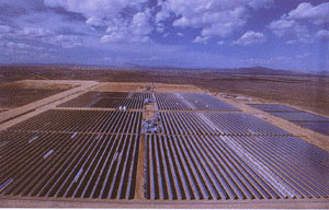
Even in such heavy energy consuming countries like USA solar energy
falling on the land mass can many times surplus the energy consumed
there. If only 1% of land would be set aside and covered by solar systems (such
as solar cells or solar thermal troughs) that were only 10% efficient, the
sunshine falling on these systems could supply this nation with all the energy
it needed. The same is true for all other developed countries. In a certain
sense, it is impractical - besides being extremely expensive, it is not
possible to cover such large areas with solar systems. The damage to
ecosystems might be dramatic. But the principle remains. It is possible to
cover the same total area in a dispersed manner - on buildings, on houses,
along roadsides, on dedicated plots of land, etc. In another sense, it is
practical. In many countries already more than 1% of land is dedicated to the
mining, drilling, converting, generating, and transporting of energy. And the
great majority of this energy is not renewable on a human scale and is far more
harmful to the environment than solar systems would prove to be.
![]()
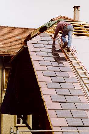
SOLAR ENERGY UTILISATION
In most places of the world much more solar energy hits a home's roof and
walls as is used by its occupants over a year's time. Harnessing this sun's
light and heat is a clean, simple, and natural way to provide all forms of
energy we need. It can be absorbed in solar collectors to provide hot water or
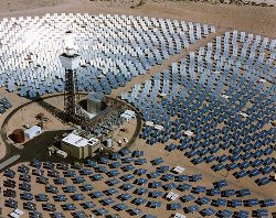
space heating in households and commercial buildings. It can be concentrated by
parabolic mirrors to provide heat at up to several thousands degrees Celsius.
This heat can be used either for heating purposes or to generate electricity.
There exist also another way to produce power from the sun - through
photovoltaics. Photovoltaic cells are devices which convert solar radiation
directly into electricity.
Solar radiation can be converted into useful energy using active systems and passive solar design. Active systems are generally those that are very visible like solar collectors or photovoltaic cells. Passive systems are defined as those where the heat moves by natural means due to house design which entails the arrangement of basic building materials to maximize the sun's energy.
Solar energy can be converted to useful energy also indirectly, through other energy forms like biomass, wind or hydro power. Solar energy drives the earth´s weather. A large fraction of the incident radiation is absorbed by the oceans and the seas, which are warmed than evaporate and give the power to the rains which feed hydro power plants. Winds which are harnessed by wind turbines are getting its power due to uneven heating of the air. Another category of solar-derived renewable energy sources is biomass. Green plants absorb sunlight and convert it through photosynthesis into organic matter which can be used to produce heat and electricity as well. Thus wind, hydro power and biomass are all indirect forms of solar energy.
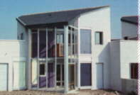
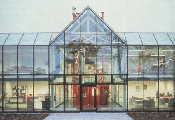
Passive solar design, or climate responsive buildings use
existing technologies and materials to heat, cool and light buildings. They
integrate traditional building elements like insulation, south-facing glass,
and massive floors with the climate to achieve sustainable results. These
living spaces can be built for no extra cost while increasing affordability
through lower energy payments. In many countries they also keep investment in
the local building industry rather than transferring them to short term energy
imports. Passive solar buildings are better for the environment while
contributing to an energy independent, sustainable energy future.
Passive solar system uses the building structure as a collector, storage and
transfer mechanical equipment. This definition fits most of the more simple
systems where heat is stored in the basic structure: walls, ceiling or floor.
There are also systems that have heat storage as a permanent element within the
building structure, such as bins of rocks, or water-filled drums or bottles.
These are also classified as passive solar energy systems. Passive solar homes
are ideal places in which to live. They provide beautiful connections to the
outdoors, give plenty of natural light, and save energy throughout the year.
HISTORY
Building design has historically borrowed its inspiration from the local
environment and available building materials. More recently, humankind has
designed itself out of nature, taking a path of dominance and control which led
to one style of building for nearly any situation. In 100 A.D., Pliny the
Younger, a historical writer, built a summer home in Northern Italy featuring
thin sheets of mica windows on one room. The room got hotter than the others
and saved on short supplies of wood. The famous Roman bath houses in the first to
fourth centuries A.D. had large south facing windows to let in the sun's
warmth. By the sixth century, sunrooms on houses and public buildings were so
common that the Justinian Code initiated sun rights to ensure individual
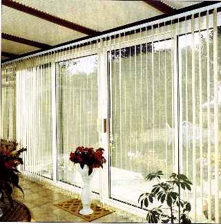
access to the sun. Conservatories were very popular in the 1800's creating
spaces for guests to walk through warm greenhouses with lush foliage.
Passive solar buildings in the United States were in such demand by 1947, as a result of scarce energy during the prolonged World War 2, that Libbey-Owens-Ford Glass Company published a book entitled Your Solar House, which profiled forty-nine of the nations greatest solar architects.
In the mid-1950's, architect Frank Bridgers designed the world's first
commercial office building using solar water heating and passive design. This
solar system has been continuously operating since that time and the Bridgers-Paxton
Building is now in the National Historic Register as the world's first solar
heated office building.
Low oil prices following World War 2 helped keep attention away from solar
designs and efficiency. Beginning in the mid-1990's, market pressures are
driving a movement to redesign our building systems to more in line with
nature.
![]()
Passive Solar Space Heating
|
|
There are few basic architectural modes for the
utilisation of passive solar utilisation in architecture. But these modes, as
presented below, can be developed into many different scheme, and enrich the
design. |
Site
Landscaping and Trees
According to the U.S. Department of Energy report, Landscaping for Energy
Efficiency (DOE/GO-10095-046), careful landscaping can save up to 25% of a
household's energy consumption for heating and cooling. Trees are very
effective means of shading in the summer months as well as providing breaks for
the cool winter winds. In addition to contributing shade, landscape features
combined with a lawn or other ground cover can reduce air temperatures as much
as 5 degrees Celsius in the surrounding area when water evaporates from
vegetation and cools the surrounding air. Trees are wonderful for natural
shading and cooling, but they must be located appropriately so as to provide
shade in summer and not block the winter sun. Even deciduous trees that lose
their leaves during cold weather block some winter sunlight - a few bare trees
can block over 50 percent of the available solar energy.
Windows
|
|
All effective passive systems depend on windows. Glass or other translucent materials allow short-wave, solar radiation to enter a building and prohibit the long-wave, heat radiation, from escaping. Windows control the energy flow in two principle ways: they admit solar energy in winter, so warming the house above the otherwise cool to cold internal conditions; and by excluding sun from the windows (by orientation and shading) there exist the opportunity to use ventilation to cool the otherwise warm hot house in summer. If use is to be made of the sun's heat, then it has to reach buildings when it is useful. Generally, the sun should be able to reach the collection area between 9 a.m. and 3 p.m. in winter with as little obstruction and interference as possible.Trees on the site or the neighbours' site might shade the vital areas of the building. This need to be checked and the building located to minimise any such interference. It is possible to plan a house to have its main outlook in any direction and still be an efficient low energy building. The building envelope, i.e. the walls, floor and roof are the important elements in design, rather than the location of internal spaces. If a window needs to face west it requires correct shading and its size restricted. |
Glass permits sun radiation of wavelengths 0.4 to 2.5 microns to pass through it. As this radiant energy collides with opaque objects on the other side of the glass, it's wavelength increases to 11 microns. Glass acts as an opaque barrier to light of this wavelength thereby trapping the sun's energy. The amount of light penetrating a glass is dependent on the angle of incidence. The optimum angle of incidence is 90o. When sunlight strikes the glass at 30o or less, the most radiation is reflected.

![]()
Understanding the Solar
Spectrum and Heat Transfer
To make good choices on glazing, it is needed to understand a bit about
light and heat. The sunlight that strikes the Earth is comprised of a variety
of wavelengths and different glazing will selectively transmit, absorb, and
reflect the various components of the solar spectrum. Likewise, reducing glare
(via reflection or tinting) is helpful in the workplace by allowing the
transmission of visible, or natural, light it is possible to save energy for
artificial light. But perhaps the greatest effect on human comfort levels is
determined by infrared heat transfer. By specifying the right type of glass, it
is possible to trap the infrared heat for warmth, or reflect the infrared heat
to prevent warming.
There are three ways that heat moves through a glazing material. The
first is conduction. Conductive heat is transferred through the glazing by
direct contact. Heat can be felt by touching the glazing material. The second
form of heat transfer is radiation; electromagnetic waves carry heat through a
glazing. This produces the feeling of heat radiating from the surface of the
glazing. The third method of heat transfer is convection. Convection transfers
heat by motion, in this case, air flow. The natural flow of warm air toward
colder air allows heat to be lost or gained.
The R-value of a glazing - its insulating capabilities or resistance to the
flow of heat - is determined by the degree of conduction, radiation, and
convection through the glazing material. However, air infiltration will also
determine the overall R-value of a glazing system. The amount of heat that
travels around a glazing is as important as the heat transfer through a
glazing. Air can leak in or out of a building around the glazing via the
framing. The quality, workmanship, and the installation of the entire glazing
system, including the framing, affects air infiltration.
Advances in glass technology have perhaps been the single largest contributor
to building efficiency since the 1970s and they play an important roll in solar
design. Some window advances include:
![]() Double
and triple pane windows with much higher insulating values.
Double
and triple pane windows with much higher insulating values.
![]() Low
emissivity or Low-E glass employing a coating which lets heat in but not out.
Low
emissivity or Low-E glass employing a coating which lets heat in but not out.
![]() Argon
(and other) gas filled windows that increase insulating values above windows
with just air.
Argon
(and other) gas filled windows that increase insulating values above windows
with just air.
![]() Phase-change
technologies that can switch from opaque to translucent when a voltage is
applied to them.
Phase-change
technologies that can switch from opaque to translucent when a voltage is
applied to them.
Basic Glass Types
Glazing materials include glass, acrylics, fibreglass, and other materials.
Although different glazing materials have very specific applications, the use
of glass has proven the most diverse. The various types of glass allow the
passive solar designer to fine-tune a structure to meet client needs. The
single pane is the simplest of glass types, and the building block for higher
performance glass. Single panes have a high solar transmission, but have poor
insulation - the R-value is about 1,0. Single pane glass can be effective when
used as storm windows, in warm climate construction (unless air conditioning is
being used), for certain solar collectors, and in seasonal greenhouses.
Structures using single pane glass will typically experience large temperature
swings, drafts, increased condensation, and provide a minimal buffer from the
outdoors.
Perhaps the most common glass product used today is the double pane unit.
Double pane glass is just that: two panes manufactured into one unit. Isolated
glass (thermopane) incorporate a spacer bar (filled with a moisture absorbing
material called a desiccant) between the panes and are typically sealed with
silicone. The spacer creates a dead air space between the panes. This air space
increases the resistance to heat transfer; the R-value for double pane is about
1,8-2,1. Huge air spaces will not drastically increase R-value. In fact, a
large air space can actually encourage convective heat transfer within the unit
and produce a heat loss. A rule of thumb for air space is between 1 and 2
centimetres. It is also possible to go as large as 10-12 centimetres without
creating convective flow, but at that point you are dealing with a very large
and awkward unit. The demand for greater energy efficiency in building and
retrofitting homes has made insulated glass units the standard. With good solar
transmission and fair insulation, such unit is a large improvement over the
single pane. Windows, doors, skylights, sunrooms, and many other areas utilize
double pane glass.
![]()
HIGH PERFORMANCE GLASS
High performance or enhanced glass offers even better R-value and solar
energy control. By further improving the insulating capability of glass, it is
possible dramatically increase also design options. What were once
insulated walls may become sunrooms. Solid roofs and ceilings become windows to
the sky. Dark rooms can wake up to natural light, solar heat gain, and
wonderful views. For a relatively small increase in cost it is possible to
improve efficiency, provide better moisture and UV protection, and gain design
flexibility. A variety of high performance glass is now available.
What are the advantages of this glass? Low emissivity (Low-E) glass is succeeding double pane glass in energy efficient buildings. Emissivity is the measure of infrared (heat) transfer through a material. The higher the emissivity, the more heat is radiated through the material. Conversely, the lower the emissivity, the more heat is reflected by the material. Low-E coatings will reflect, or re-radiate, the infrared heat back into a room, making the space warmer. This translates into R-values from 2.6 to 3.2. In warmer climates it is possible to reverse the unit and re-radiate infrared heat back to the outside, keeping the space cooler. Low-E glass improves the R-value, UV protection, and moisture control.Gas-filled windows increase R-value. Properly done, gas-filling will increase the overall R-value of a glass unit by about 1,0. The air within an insulated glass unit is displaced with an inert, harmless gas with better insulation properties. Typical gases used are Krypton and Argon.
Window curtains
In addition to decorative functions, curtains can be used to reduce the heat
losses that occur during the cold months as well as the heat gains during the
warmer months. The plywood box over the curtain top prevents warm ceiling air
from moving between the glass and curtain. The curtain should drop at least 30
cm below the window for it to be effective. The optimum condition would be for
it to drop to the floor.
Thermal mass
Solar radiation hitting walls, windows, roofs and other surfaces is adsorbed
by the building and is stored in thermal mass. This stored heat is then
radiated to the interior of the building. Thermal mass in a solar heating
system performs the same function as batteries in a solar electric system (see
chapter on photovoltaics). Both store solar energy, when available, for later
use.
Thermal mass can be incorporated into a passive solar room in many ways, from tile-covered floors to water-filled drums. Thermal mass materials, which include slab floors, masonry walls, and other heavy building materials, absorb and store heat. They are a key element in passive solar homes. Homes with substantial south-facing glass areas and no thermal storage mass do not perform well.
It is important to know that dark surfaces reflect less, therefore, absorb more heat. In case of a dark tiled floor, the floor will be able to absorb heat all day and radiate heat into the room at night. The rate of heat flow is based on the temperature difference between heat source and the object to which the heat flows. As described above heat flows in three ways - conduction (heat transfer through solid materials), convection (heat transfer through the movement of liquids or gasses), and radiation. All surfaces of a building lose heat via these three modes. Good solar design works to minimize heat loss and maximize efficient heat distribution. The need for thermal mass (heat-storage materials) inside a building is very climate-dependent. Heavy buildings of high thermal mass are consistently more comfortable during hot weather in hot-arid and cool-temperate climates, while in hot-humid climates there is little benefit. In cool-temperature climates the thermal mass acts as a cold-weather heat store thus improving overall comfort and reducing the need for auxiliary heating, except on overcast or very cold days. In intermittently heated buildings, however, it tends to increase the heat needed to maintain the chosen conditions.
Providing adequate thermal mass is usually the greatest challenge to the
passive solar designer. The amount of mass needed is determined by the area of
south-facing glazing and the location of the mass. In order to ensure an
effective design it is important to follow these guidelines:
![]() Locate the thermal mass in
direct sunlight. Thermal mass installed where the sun can reach it directly is more
effective than indirect mass placed where the sun's rays do not penetrate.
Houses that rely on indirect storage need three to four times more thermal mass
than those using direct storage.
Locate the thermal mass in
direct sunlight. Thermal mass installed where the sun can reach it directly is more
effective than indirect mass placed where the sun's rays do not penetrate.
Houses that rely on indirect storage need three to four times more thermal mass
than those using direct storage.
![]() Distribute the thermal mass.
Passive solar homes work better if the thermal mass is relatively thin and
spread over a wide area. The surface area of the thermal mass should be at
least 3 times, and preferably 6 times, greater than the area of the south
windows. Slab floors that are 8 to 10 centimetres thick are more cost effective
and work better than floors 16 to 20 inches thick.
Distribute the thermal mass.
Passive solar homes work better if the thermal mass is relatively thin and
spread over a wide area. The surface area of the thermal mass should be at
least 3 times, and preferably 6 times, greater than the area of the south
windows. Slab floors that are 8 to 10 centimetres thick are more cost effective
and work better than floors 16 to 20 inches thick.
![]() Do not cover the thermal mass.
Carpeting virtually eliminates savings from the passive solar elements. Masonry
walls can have drywall finishes, but should not be covered by large wall
hangings or lightweight panelling. The drywall should be attached directly to
the mass wall, not to covers fastened to the wall that create an undesirable
insulating airspace between the drywall and the mass.
Do not cover the thermal mass.
Carpeting virtually eliminates savings from the passive solar elements. Masonry
walls can have drywall finishes, but should not be covered by large wall
hangings or lightweight panelling. The drywall should be attached directly to
the mass wall, not to covers fastened to the wall that create an undesirable
insulating airspace between the drywall and the mass.
![]() Select an appropriate mass
colour. For best performance, finish mass floors with a dark colour. A medium
colour can store 70 percent as much solar heat as a dark colour, and may be
appropriate in some designs. A matte finish for the floor reduces reflected
sunlight, thus increasing the amount of heat captured by the mass and having
the additional advantage of reducing glare. The colour of interior mass walls
does not significantly affect passive solar performance.
Select an appropriate mass
colour. For best performance, finish mass floors with a dark colour. A medium
colour can store 70 percent as much solar heat as a dark colour, and may be
appropriate in some designs. A matte finish for the floor reduces reflected
sunlight, thus increasing the amount of heat captured by the mass and having
the additional advantage of reducing glare. The colour of interior mass walls
does not significantly affect passive solar performance.
![]() Insulate the thermal mass
surfaces. There are several techniques for insulating slab floors and masonry
exterior walls. These measures should introduced to achieve the energy
savings. Unfortunately, problems in some case can arise like with termite
infestations in foam insulation for perimeter slabs. This can complicate the
issue of whether and how to insulate slab-on-grade floors.
Insulate the thermal mass
surfaces. There are several techniques for insulating slab floors and masonry
exterior walls. These measures should introduced to achieve the energy
savings. Unfortunately, problems in some case can arise like with termite
infestations in foam insulation for perimeter slabs. This can complicate the
issue of whether and how to insulate slab-on-grade floors.
![]() Make thermal mass multipurpose.
For maximum cost effectiveness, thermal mass elements should serve other
purposes as well. Masonry thermal storage walls are one example of a passive
solar design that is often cost prohibitive because the mass wall is only
needed as thermal mass. On the other hand, tile-covered slab floors store heat,
serve as structural elements, and provide a finished floor surface. Masonry
interior walls provide structural support, divide rooms, and store heat.
Make thermal mass multipurpose.
For maximum cost effectiveness, thermal mass elements should serve other
purposes as well. Masonry thermal storage walls are one example of a passive
solar design that is often cost prohibitive because the mass wall is only
needed as thermal mass. On the other hand, tile-covered slab floors store heat,
serve as structural elements, and provide a finished floor surface. Masonry
interior walls provide structural support, divide rooms, and store heat.
![]()
When developing a thermal storage system or simply comparing materials it
is useful to look at the storage capacity of the proposed building materials
which is referred to as the volumetric heat capacity (J/m3. Deg. Celsius) or
more commonly the specific heat and the rate at which the material can take up
and store heat. Some examples of common storage materials are given in the
following table:
|
Material |
Density (kg/m3) |
Volumetric heat capacity (J/m3. Deg. C) |
|
Water |
1000 |
4186 |
|
Concrete |
2100 |
1764 |
|
Brick |
1700 |
1360 |
|
Stone: marble |
2500 |
2250 |
|
|
Materials not suitable for thermal storage |
|
|
Plasterboard |
950 |
798 |
|
Timber |
610 |
866 |
|
Glass fibre matt |
25 |
25 |
Early solar designers used water (stored in large containers) as the heat storage medium. Although water is cheap, the containers and the space they take are not. Some solar designers turned to rock storage bins as reservoirs for thermal mass. It took three times as much rock to store the same amount of heat as an equivalent volume of water and the moist warm environment of the bins became breeding grounds for odor producing fungi and bacteria. The high cost and the foul odors started to give solar design a bad name. Both water and rock heat storage require complicated control systems, pumps, and blowers. Heat storage is not common in todays solar energy utilisation. Main reason for this is that all of these systems rely on electricity, require maintenance, and are subject to periodic breakdown.
Thermal insulation
|
|
Materials generally available for building purposes can be classified into two generic groups - bulk materials and reflective foil laminates (RFL). The first of these relies on the resistance of air trapped in pockets between the fibres of the blanket type materials (mineral fibre materials) or the cells formed in the foamed structure of board or slab type materials (usually made from plastics such as polystyrene and polyurethane foams). The second reflects radiant energy away from the object or surface being protected. Thermal insulation in the outer fabric of a building is a vital component of an energy-efficient design strategy. The key to successful energy-efficient design is the control of heat flow through the external fabric. All the solar energy gained could be easily lost from an inadequately insulated building before it is able to be of benefit. It will have been noted that some materials have a very much higher thermal resistance per unit thickness than others irrespective of their density. The fact that air is a good insulator especially if it is bounded by a bright foil surface to limit radiation transfer can be very useful as well. |
Cooling
In many parts of the world a passive solar building needs cooling as much as
heating. One of the best, time proven methods of cooling is thermal coupling
with the earth's constant temperature. Dropping the ground floor at least one
meter into the earth provides a more even exterior temperature which aids
cooling as well as heating. Adequate structural engineering, drainage, and damp
proofing are essential in below ground areas. Thermal isolation is the best and
most economical way to temper the building's environment. Using the earth's
thermal mass keeps the house at a reasonable temperature, and so does good
insulation. Shades located outside and inside the windows, ventilation and
reflective films on the windows are also very important in order to control
temperature inside the building.
![]()
External Shades and Shutters
Exterior window shading treatments are effective cooling measures because
they block both direct and indirect sunlight outside of the home. Solar shade screens
are an excellent exterior shading product with a thick weave that blocks up to
70 percent of all incoming sunlight. The screens absorb sunlight so they should
be used on the exterior of the windows. From outside, they look slightly darker
than regular screening, but from the inside many people do not detect a
difference. Most products also serve as insect screening. They should be
removed in winter to allow full sunlight through the windows. A more expensive
alternative to the fibreglass product is a thin, metal screen that blocks
sunlight, but still allows a view from inside to outside. Hinged decorative
exterior shutters which close over the windows are also excellent shading
options. However, they obscure the view, block daylight completely, may be
expensive and may be difficult for many households to operate on a daily basis.
Interior Shades and Shutters
Shutters and shades located inside the house include curtains, roll-down
shades, and Venetian blinds. Interior shutters and shades are generally the
least effective shading measures because they try to block sunlight that has
already entered the room. However, if passive solar windows do not have
exterior shading, interior measures are needed. The most effective interior
treatments are solid shades with a reflective surface facing outside. In fact,
simple white roller blinds keep the house cooler than more expensive louvered
blinds, which do not provide a solid surface and allow trapped heat to migrate
between the blinds into the house.
Reflective Films and Tints
Reflective film, which adheres to glass and is found often in commercial
buildings, can block up to 85% of incoming sunlight. The film blocks sunlight
all year, so it is inappropriate on south windows in passive solar homes.
However, it may be practical for unshaded east and west windows. These films
are not recommended for windows that experience partial shading because they
absorb sunlight and heat the glass unevenly. The uneven heating of windows may
break the glass or ruin the seal between double-glazed units.
Ventilation
Ventilation is the changing of air in buildings to control oxygen, heat and
contaminants. Ventilation may occur in few forms. Building orientation, form,
plan and user actions also alter air flow paths. Natural ventilation consumes
no energy and has few if any running costs, but depends on weather conditions
and can be difficult to control. Mechanical and air-conditioned ventilation are
energy-driven alternatives to natural ventilation, normally dictated by
building type, site and function. They can be particularly efficient as
supplements to natural ventilation. Mechanical ventilation uses fans and ducts
to supply and extract air in localised areas such as a kitchen. Air
conditioning both treats and supplies air. It is particularly useful to cool
air below ambient temperatures.
SOLAR ARCHITECTURE &
ACTIVE SYSTEMS
It is important to design the house with the aim to incorporate active solar
systems (see below) like collectors or photovoltaic modules as well. The
building should orient these appliances due south. Tilt of the solar collectors
should be in Europe and North America more than 50° (from horizontal) to
maximize winter heat collection. Solar collectors should be thermally locked
with the roof. Non-tracking photovoltaics receive the most yearly insolation
(exposure to the sun's rays) when tilted at an angle, from horizontal, equal to
the building's latitude. Design of the building's roof should be done to such
angles and southern orientation as integral aspects of the building. Hot water
collectors and photovoltaic panels should be located as close as possible to
their main areas of use. It is important to concentrate these areas of use. For
example, putting the bathrooms and kitchen close together economizes on their
installation and minimizes energy loss. All appliances should be selected with
efficiency as the prime criterion.
![]()
SUMMARY
|
|
Passive use of sunlight contributes around 15% of space heating needs in typical building. It is important source of energy savings which can be utilised everywhere and almost at no extra cost. There are some principles which can help a designer to harness solar energy through thermally efficient buildings. |
SITE
It is important to become familiar with the energy flows of house
surroundings. The nature and relationship of the lay of the land, water
courses, vegetation, soil types, wind directions, and exposure to the sun
should be investigated. A site suitable for solar design should balance and
complement these elements. It must have unobstructed exposure to the sun from 9
am to 3 pm during the heating season.
HEATING
In Northern hemisphere orientation due south of the main solar insolating
spaces, i.e. greenhouse, and/or main daytime activity areas is important. Glass
should be open to the sun patterns during the winter. By facing of the windows
to the south, and virtually none to the north maximaze solar gain. Multiple
pane glass in all windows is recommended.
THERMAL MASS
Thermal mass including masonry floors, walls and water storage is important
to absorb ambient heat during the day and release it at night. Insulation of
the building further minimize heat loss through windows, walls and roof.
NATURAL HEAT FLOW
It is useful to design the house with the natural heat flow in mind. Hot air
rises, so placing some activity areas on a second floor to draw heat up
from a lower collector area and across other areas can save a lot of energy.
Buffer areas of the building (unheated rooms, or partially heated spaces such
as utility rooms, vestibules and storage areas) should be oriented due to the north
to lessen the impact of the winter's cold. Using a vestibule on doors to the
exterior can lead to energy savings. Vestibules cut heat loss and provide a
buffer zone between the exterior and the interior.
Using energy from the sun to heat water is one of the
oldest uses of solar energy. Solar collectors are the heart of most solar energy
systems. The collector absorbs the sun's light energy and changes it into heat
energy. This energy is than transferred to a fluid or air which are used to
warm buildings, heat water, generate electricity, dry crops or cook food. Solar
collectors can be used for nearly any process that requires heat.
Domestic hot water is the second-highest energy cost in the typical
household in Europe or North America. In fact, for some homes it can be the
highest energy expenditure. Solar water heating can reduce domestic water
heating costs by as much as 70%. Designed to pre-heat the domestic water that
is supplied to conventional water collector, it can result in remarkable savings.
It's easy to install and almost maintenance free.
Today, solar water heating systems are being used for single family houses,
apartment buildings, schools, car washes, hospitals, restaurants,
agricultural farms and different industries. This is a diverse list of private,
commercial and industrial buildings, but they all have one thing in common
- they all use hot water. Owners of these buildings have found that
solar water heating systems are cost-effective in meeting their hot water needs
all over the world.

![]()
HISTORY
Solar water heating was used long before fossil fuels dominated our energy
system. The principles of solar heat have been known for thousands of years. A
black surface gets hot in the sun, while a lighter coloured surface remains
cooler, with white being the coolest. This principle is used by solar water collectors
which are one of the best known applications for the direct use of the sun's
energy. They were developed some two hundred years ago and the first known flat
plate collector was made by Swiss scientist Horace de Saussure in 1767, later
used by Sir John Herschel to cook food during his South Africa expedition in
the 1830's.
Solar technology advanced to roughly it's present design in 1908 when
William J. Bailey of the Carnegie Steel Company (USA), invented a
collector with an insulated box and copper coils. This collector was very
similar to the thermosyphon system (described bellow). Bailey sold 4000
units by the end of World War I and a Florida businessperson who bought the
patent rights sold nearly 60 000 units by 1941. In the U.S. the rationing of
copper during World War II sent the solar water heating market into a sharp
decline.
Little interest was shown in such devices until the world-wide oil crisis of
1973. This crisis promoted new interest in alternative energy sources. As a
result, solar energy has, received increased attention and many countries are
taking a keen interest in new developments. The efficiency of solar heating
systems and collectors has improved from the early 1970s. The efficiencies can
be attributed to the use of low-iron, tempered glass for glazing (low-iron
glass allows the transmission of more solar energy than conventional glass),
improved insulation, and the development of durable selective coatings.
SOLAR COLLECTOR MARKET
 Solar domestic hot-water
systems are technically mature and available practically all over the world.
The market for flat-type collectors has been reported as substantial in Israel,
China, Cyprus, Japan, Australia, Austria, Germany, Greece Turkey and USA. Sales
in Europe are mainly for domestic water heating, which may also include space
heating and heating swimming pools. World production of solar collectors in
1995 was 1,3 million m2 where market in Europe and Mediterranean countries is
reported to be about 40% of the world market. Total amount of installed solar
collectors exceeded 30 million m2 and the development of sales was very rapid
since 1980. Since 1989 there is steady increase with around 20 % per year.
Solar domestic hot-water
systems are technically mature and available practically all over the world.
The market for flat-type collectors has been reported as substantial in Israel,
China, Cyprus, Japan, Australia, Austria, Germany, Greece Turkey and USA. Sales
in Europe are mainly for domestic water heating, which may also include space
heating and heating swimming pools. World production of solar collectors in
1995 was 1,3 million m2 where market in Europe and Mediterranean countries is
reported to be about 40% of the world market. Total amount of installed solar
collectors exceeded 30 million m2 and the development of sales was very rapid
since 1980. Since 1989 there is steady increase with around 20 % per year.
Among countries in Europe, Greece has become the leader in production of
solar systems and exports 40% of all collectors produced and comprises 30% of
the market in Germany. The industrys goal for the year 2005 represents
1,3 million systems and 5 million m2 of collectors. A project on Crete
will need 20,000 collectors over two years. The Greek market installs
70,000 solar systems a year, reducing CO2 emissions by 1,5 million tonnes.
Sales in the EU in 1996 were reported to be over 0,7 million m2 of glazed
collectors and about 0,15 million m2 of unglazed collectors (Renewable energy
world, Sept. 1998). All the indications are that this trend will continue at a
rapid pace since measures are being taken all over the EU for the promotion of
solar systems.
![]()
Installed solar collector area in the world (Source: IEA SHC programme: Solar Thermal Collector Market in IEA Member Countries, December 2002)
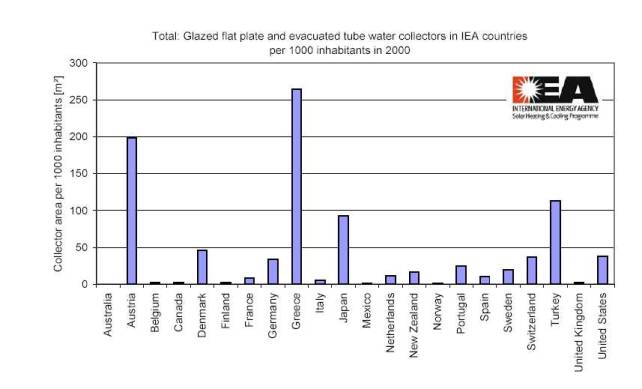
Installed solar collector area per head of population was 0,5 m2 in Cyprus in 2002 the largest in Europe and followed by Greece and Austria. Collector area per head of population increased in Austria up to 0,2 m2 in 2002 and amounted total area of 1,5 million m2. Austria is first in sales per capita followed by Greece but both countries still fall behind the world leaders Israel and Cyprus. Analysis of statistical figures like collector area per head of population shows that favourable climatic conditions have less influence than socio-economic boundary conditions. The success in Cyprus is explained not only by the absence of any other local source of energy but also by countries regulation. Strong legislation promoting solar energy utilisation is in force also in Israel. Israel and Cyprus have imposed statutory requirements for solar heating systems in all new buildings. These requirements were introduced in stages: thus in Israel initially all new apartment buildings of up to eight storeys were required to have a community solar water heating system with appropriate storage tanks. This was later extended to all new dwellings in the country. Finally in 1983 new regulations required hotels, hospitals and schools to install solar water heating equipment. These regulations were coupled with financial incentives. A similar attempt has also been made in Cyprus and it was recently estimated that 90 % of individual dwellings and 15 % of apartments in Cyprus are now equipped with solar water heaters.
POTENTIALS
In Europe the total rapidly exploitable potential for solar collectors
production is estimated to be 360 million m2 , representing a market volume of
50 billion USD at an annual average growth rate of 23%. In 2005 the area
occupied by glazed solar collector installations in the EU was expected to rise
to 28 million m2. Moreover, unglazed solar collectors for heating swimming
pools are expected to reach 20 million m2.
![]()
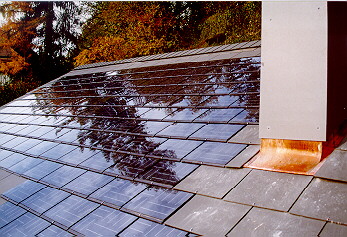
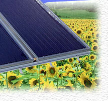
SOLAR COLLECTORS TYPES
Typical solar collectors collect the sun's energy usually with rooftop
arrays of piping and net metal sheets, painted black to absorb as much
radiation as possible. They are encased in glass or plastic and angled towards south
to catch maximum sunshine. The collectors act as miniature greenhouses,
trapping heat under their glass plates. Because solar radiation is so diffuse,
the collectors must have a large area.
Solar collectors can be made in various sizes and constructions depending
on requirements. They give enough hot water for washing, showers and cooking.
They can be used also as pre-heaters for existing water heaters. Today there
are several collectors on the market. They can be divided into several
categories. One of them is division according temperature they produce:
![]() Low-temperature collectors
provide low grade heat, less than 50 degrees Celsius, through either metallic
or non-metallic absorbers for applications such as swimming pool heating and
low-grade water.
Low-temperature collectors
provide low grade heat, less than 50 degrees Celsius, through either metallic
or non-metallic absorbers for applications such as swimming pool heating and
low-grade water.
![]() Medium-temperature collectors
provide medium to high-grade heat (greater than 50 degrees Celsius, usually 60
to 80 degrees), either through glazed flat-plate collectors using air or liquid
as the heat transfer medium or through concentrator collectors that concentrate
the heat to levels greater than one sun. These include evacuated tube
collectors, and are most commonly used for residential hot water heating.
Medium-temperature collectors
provide medium to high-grade heat (greater than 50 degrees Celsius, usually 60
to 80 degrees), either through glazed flat-plate collectors using air or liquid
as the heat transfer medium or through concentrator collectors that concentrate
the heat to levels greater than one sun. These include evacuated tube
collectors, and are most commonly used for residential hot water heating.
![]() High-temperature collectors are
parabolic dish or trough collectors primarily used by independent power
producers to generate electricity for the electric grid.
High-temperature collectors are
parabolic dish or trough collectors primarily used by independent power
producers to generate electricity for the electric grid.
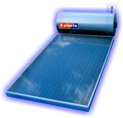
Batch Solar Water Collectors
|
|
The simplest type of solar water collector is a batch collector, so called because the collector is the storage tank - water is heated and stored a batch at a time. Batch collectors are used as pre-heaters for conventional or instantaneous water heaters. When hot water is used in the household, solar-preheated water is drawn into the conventional water collector. Since the water has already been heated by the sun, this reduces energy consumption. A batch solar water collector is a low cost alternative to an active solar hot water system, offering no moving parts, low maintenance, and zero operational cost. The acronym for a batch type solar water collector is ICS, meaning Integrated Collector and Storage. Batch collectors, also known as breadbox , use one or more black tanks filled with water and placed in an insulated, glazed box. Some boxes include reflectors to increase the solar radiation. Solar energy passes through the glazing and heats the water in the tanks. These devices are inexpensive solar water collectors but must be drained or protected from freezing when temperatures drop below freezing. |
Flat-Plate Collectors
 Flat-plate collectors are the
most common collectors for residential water heating and space-heating installations.
A typical flat-plate collector is an insulated metal box with a glass or
plastic cover called the glazing and a dark-coloured absorber plate. The
glazing can be transparent or translucent. Translucent (transmitting light
only) low-iron glass is a common glazing material for flat-plate collectors
because low-iron glass transmits a high percentage of the total available solar
energy. The glazing allows the light to strike the absorber plate but reduces
the amount of heat that can escape. The sides and bottom of the collector are
usually insulated, further minimising heat loss.
Flat-plate collectors are the
most common collectors for residential water heating and space-heating installations.
A typical flat-plate collector is an insulated metal box with a glass or
plastic cover called the glazing and a dark-coloured absorber plate. The
glazing can be transparent or translucent. Translucent (transmitting light
only) low-iron glass is a common glazing material for flat-plate collectors
because low-iron glass transmits a high percentage of the total available solar
energy. The glazing allows the light to strike the absorber plate but reduces
the amount of heat that can escape. The sides and bottom of the collector are
usually insulated, further minimising heat loss.
The absorber plate is usually black because dark colours absorb more solar
energy than light colours. Sunlight passes through the glazing and strikes the
absorber plate, which heats up, changing solar radiation into heat energy. The
heat is transferred to the air or liquid passing through the flow tubes.
Because most black paints still reflect approximately 10% of the incident radiation
some absorber plates are covered with selective coatings, which retain the
absorbed sunlight better and are more durable than ordinary black paint. The
selective coating used in the collector consists of a very precise thin layer
of an amorphous semiconductor plated on to a metal substratum. Selective
coatings has both high absorptivity in the visible region and low emissivity in
the long-wave infrared region.
Absorber plates are often made of metal usually copper or aluminium because
they are both good heat conductors. Copper is more expensive, but is a better
conductor and is less prone to corrosion than aluminium. An absorber plate must
have high thermal conductivity, to transfer the collected energy to the water
with minimum temperature loss. Flat-plate collectors fall into two basic categories:
liquid and air. And both types can be either glazed or unglazed.
![]()
Liquid Collectors
 In a liquid collector, solar
energy heats a liquid as it flows through tubes in the absorber plate. For this
type of collector, the flow tubes are attached to the absorber plate so the
heat absorbed by the absorber plate is readily conducted to the liquid.
In a liquid collector, solar
energy heats a liquid as it flows through tubes in the absorber plate. For this
type of collector, the flow tubes are attached to the absorber plate so the
heat absorbed by the absorber plate is readily conducted to the liquid.
The flow tubes can be routed in parallel, using inlet and outlet headers, or
in a serpentine pattern. A serpentine pattern eliminates the possibility of
header leaks and ensures uniform flow. A serpentine pattern can pose some
problems for systems that must drain for freeze protection because the curved
flow passages will not drain completely.
The simplest liquid systems use potable household water, which is heated as
it passes directly through the collector and then flows to the house to be used
for bathing, laundry, etc. This design is known as an open-loop (or direct)
system. In areas where freezing temperatures are common, however, liquid
collectors must either drain the water when the temperature drops or use an
antifreeze type of heat-transfer fluid.
In systems with heat-transfer fluids, the transfer fluid absorbs heat from
the collector and then passes through a heat exchanger. The heat exchanger,
which generally is in the water storage tank inside the house, transfers heat to
the water. Such designs are called closed-loop (or indirect) systems.
Glazed liquid collectors are used for heating household water and sometimes
for space heating. Unglazed liquid collectors are commonly used to heat water
for swimming pools. Because these collectors need not withstand high
temperatures, they can use less expensive materials such as plastic or rubber.
They also do not require freeze-proofing because swimming pools are generally
used only in warm weather.
Air Collectors
Air collectors have the advantage of eliminating the freezing and boiling
problems associated with liquid systems. Although leaks are harder to detect
and plug in an air system, they are also less troublesome than leaks in a
liquid system. Air systems can often use less expensive materials, such as
plastic glazing, because their operating temperatures are usually lower than
those of liquid collectors.
Air collectors are simple, flat-plate collectors used primarily for space
heating and drying crops. The absorber plates in air collectors can be metal
sheets, layers of screen, or non-metallic materials. The air flows through the
absorber by natural convection or when forced by a fan. Because air conducts
heat much less readily than liquid does, less heat is transferred between the
air and the absorber than in a liquid collector. In some solar air-heating
systems, fans on the absorber are used to increase air turbulence and improve
heat transfer. The disadvantage of this strategy is that it can also increase
the amount of power needed for fans and, thus, increase the costs of operating
the system. In colder climates, the air is routed between the absorber plate
and the back insulation to reduce heat loss through the glazing. However, if
the air will not be heated more than 17°C above the outdoor temperature, the air
can flow on both sides of the absorber plate without sacrificing efficiency.
The best features of air collector systems are simplicity and reliability.
The collectors are relatively simple devices. A well-made blower can be
expected to have a 10 to 20 year life span if properly maintained, and the
controls are extremely reliable. Since air will not freeze, no heat exchanger
is required.
However, the use of solar air heating collectors is still limited to supply
hot air for space heating and for drying of agricultural products mainly in
developing countries. The major limitations for the wide adoption of solar air
heaters are the high cost for commercially produced solar air heaters, the
large collector area required due to the low density and the low specific heat
capacity of the air compared to liquid heat transfer fluids, the extended air
duct system required, the high power requirement for forcing the air through
the collector, and the difficulty of heat storage. In countries with
comparatively low insolation and extended periods of adverse weather,
supplementary heat is required which increases investment costs to a level
which limits its competitiveness to conventional heating systems. Promising
ways to reduce the collector cost are the integration of the collector into the
walls or roofs of buildings and the development of collectors which can be
constructed using prefabricated components.
Solar wall.
![]()

Heating with the solar wall .

![]()
HOW IT WORKS ?
Solar air heaters can be classified based on the mode of air circulation. In
the bare plate collector, which is the most simple solar air heater, the air
passes through the collector underneath the absorber. This kind of solar air
heater is only suitable for temperature rise between 3 - 5 deg. Celsius due to
the high convection and radiation losses at the surface. The top losses can be
reduced significantly by covering the absorber with a transparent material of
low transitivity for infrared radiation. The air flow occurs in this kind of
solar air heater either underneath the absorber or between absorber and
transparent cover. Due to the transparent cover, the incident radiation on the
absorber is reduced slightly, but due to the reduction of the convective heat
losses, temperature rise between 20 and 50 degrees Celsius can be achieved
depending on insolation and air flow rate. A further reduction of the heat
losses can be achieved if the air is made to pass above and underneath the
absorber since this doubles the heat transfer area. The heat losses due to
radiation will be reduced by this process due to lower absorber temperature.
However, there is simultaneous reduction in the absorptivity of the absorber
due to dust deposit if air flow is above or on both sides of the absorber.
Some solar air collectors eliminate the cost of the glazing, the metal box,
and the insulation. Such a collector is made of black, perforated metal. The
best heat transfer can be achieved by using porous material as absorber.
The sun heats the metal, and a fan pulls air through the holes in the metal,
which heats the air. For residential installations, these collectors are
available in different sizes. Typical collector 2,4-meter by 0,8-meter
panels are capable of heating 0,002 m3 per second of outside air. On a sunny
winter day, the panel can produce temperatures up to 28°C higher than the
outdoor air temperature. Transpired air collectors not only heat air, but also
improve indoor air quality by directly preheating fresh outdoor air. These
collectors have achieved very high efficiencies - more than 70% in some
commercial applications. Plus, because the collectors require no glazing or
insulation, they are inexpensive to manufacture.
Evacuated-Tube Collectors
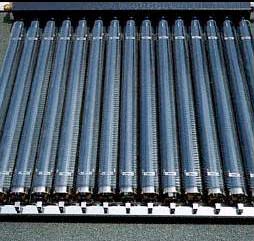 Conventional simple flat-plate
solar collectors were developed for use in sunny and warm climates. Their
benefits are greatly reduced when conditions become unfavourable during cold,
cloudy and windy days. Furthermore, weathering influences such as condensation
and moisture will cause early deterioration of internal materials resulting in
reduced performance and system failure. These shortcomings are reduced in
evacuated-tube collectors.
Conventional simple flat-plate
solar collectors were developed for use in sunny and warm climates. Their
benefits are greatly reduced when conditions become unfavourable during cold,
cloudy and windy days. Furthermore, weathering influences such as condensation
and moisture will cause early deterioration of internal materials resulting in
reduced performance and system failure. These shortcomings are reduced in
evacuated-tube collectors.
Evacuated-tube collectors heat water in residential applications that
require higher temperatures. In an evacuated-tube collector, sunlight enters
through the outer glass tube, strikes the absorber tube, and changes to heat.
The heat is transferred to the liquid flowing through the absorber tube. The
collector consists of rows of parallel transparent glass tubes, each of which
contains an absorber tube (in place of the absorber plate in a flat-plate
collector) covered with a selective coating. The heated liquid circulates
through heat exchanger and gives off its heat to water that is stored in a
solar storage tank.
Evacuated tube collectors are modular tubes which can be added or removed as
hot-water needs change. When evacuated tubes are manufactured, air is evacuated
from the space between the two tubes, forming a vacuum. Conductive and
convective heat losses are eliminated because there is no air to conduct heat
or to circulate and cause convective losses. There can still be some radiant
heat loss (heat energy will move through space from a warmer to a cooler surface,
even across a vacuum). However, this loss is small and of little importance
compared with the amount of heat transferred to the liquid in the absorber
tube. The vacuum in the glass tube, being the best possible insulation for a
solar collector, suppresses heat losses and also protects the absorber plate
and the heat-pipe from external adverse conditions. This results in
exceptional performance far superior to any other type of solar collector.

Evacuated-tube collectors are available in a number of
designs. Some use a third glass tube inside the absorber tube or other
configurations of heat-transfer fins and fluid tubes. One commercially
available evacuated-tube collector stores 19 litres of water in each tube,
eliminating the need for a separate solar storage tank. Reflectors placed
behind the evacuated tubes can help to focus additional sunlight on the
collector.
Due to the atmospheric pressure and the technical problems related to the
sealing of the collector casing, the construction of an evacuated flat-plate
collector is extremely difficult. To overcome the enormous atmospheric
pressure, many internal supports for the transparent cover pane must be
introduced. However, the problems of an effective high vacuum system with
reasonable production costs remain so far unsolved. It is more feasible to
apply and adapt the mature technology related to the lamp industries with
proven mass production. Building a tubular evacuated solar collector and the
maintenance of its high vacuum, similar to light bulbs and TV tubes, is
practical. The ideal vacuum insulation of the tubular evacuated solar
collector, obtained by means of a suitable exhausting process, has to be
maintained during the life of the device to reduce the thermal losses through
the internal gaseous atmosphere (convection losses).
In high temperature region these collectors are more efficient than
flat-plate collectors for a couple of reasons. First, they perform well in both
direct and diffuse solar radiation. This characteristic, combined with the fact
that the vacuum minimizes heat losses to the outdoors, makes these collectors
particularly useful in areas with cold, cloudy winters. Second, because of the
circular shape of the evacuated tube, sunlight is perpendicular to the absorber
for most of the day. For comparison, in a flat-plate collector that is in a
fixed position, the sun is only perpendicular to the collector at noon. Evacuated-tube
collectors achieve both higher temperatures and higher efficiencies than
flat-plate collectors, but they are also more expensive.
![]()
Concentrating Collectors
Concentrating collectors use mirrored surfaces to concentrate the sun's
energy on an absorber called a receiver. They also achieve higher temperatures
than flat-plate collectors, however concentrators can only focus direct solar
radiation, with the result being that their performance is poor on hazy or
cloudy days. The mirrored surface focuses sunlight collected over a large area
onto a smaller absorber area to achieve high temperatures. Some designs concentrate
solar energy onto a focal point, while others concentrate the sun's rays along
a thin line called the focal line. The receiver is located at the focal point
or along the focal line. A heat-transfer fluid flows through the receiver and
absorbs heat. Concentrators are most practical in areas of high insolation,
such as those close to the equator and in the desert areas.
Concentrators perform best when pointed directly at the sun. To do this,
these systems use tracking mechanisms to move the collectors during the day to
keep them focused on the sun. Single-axis trackers move east to west; dual-axis
trackers move east and west and north and south (to follow the sun throughout
the year). Concentrators are used mostly in commercial applications because
they are expensive and because the trackers need frequent maintenance. Some
residential solar energy systems use parabolic-trough concentrating systems.
These installations can provide hot water, space heating, and water
purification. Most residential systems use single-axis trackers, which are less
expensive and simpler than dual-axis trackers. For more information about
concentrating collectors see chapter Solar Thermal Power Production.
SOLAR COOKERS AND STILLS
There exists also some other inexpensive, low-tech solar collectors with
specific functions like solar box cookers (used for cooking) and solar stills
producing inexpensive distilled water from virtually any water source.
Solar box cookers (see chapter on Solar cooking) are inexpensive to buy and
easy to build and use. They consist of a roomy, insulated box lined with
reflective material, covered with glazing, and fitted with an external
reflector. Black cooking pots serve as absorbers, heating up more quickly than
aluminium or stainless steel cookware. Box cookers can also be used to kill
bacteria in water if the temperature can reach the boiling point.
Solar stills (see chapter on Solar water distillation) provide inexpensive
distilled water from even salty or badly contaminated water. They work on the
principle that water in an open container will evaporate. A solar still uses
solar energy to speed up the evaporation process. The stills consist of an
insulated, dark-coloured container covered with glazing that is tilted so the
condensing fresh water can trickle into a collection trough. A small solar
still, which is about the size of kitchen stove, can produce up to ten litres
of distilled water on a sunny day.
Technology Examples
Solar energy has a variety of practical and cost-effective applications in
today's homes and buildings. The main applications of solar collectors are as
follows :
![]() hot water preparation in
households, commercial buildings and industry,
hot water preparation in
households, commercial buildings and industry,
![]() water heating in swimming
pools,
water heating in swimming
pools,
![]() space heating in buildings,
space heating in buildings,
![]() drying crops and houses,
drying crops and houses,
![]() space cooling and
refrigeration,
space cooling and
refrigeration,
![]() water distillation,
water distillation,
![]() solar cooking.
solar cooking.
The technologies for all applications are considered to be mature and for
the first two, under the appropriate conditions, economically viable. Separate
chapter is devoted to concentrating collectors which are cost effectively used
for power production especially in regions with high insolation (see chapter on
Solar Thermal Power).
![]()
Solar Thermal Residential Water Heating

Today, several million homes and businesses use solar
water heating systems. These systems are providing consumers a cost-effective
and reliable choice for hot water. Taking a shower with solar-heated water, or
heating a house with solar-heated air or water, is a natural and simple method
for both conserving energy and saving fossil fuels. When a solar heating system
has been designed and installed correctly, it can be aesthetically appealing
and also add to the value of the home. On new construction, they can be worked
into the building design to be almost invisible, while on existing construction
it can be a real challenge to make them fit in.
A solar water collector is saving an owner money but it also help protect
the environment. Emissions of one to two tons of carbon dioxide are saved by a
single conventional water collector every year. Other pollutants, such as
sulphur dioxides, carbon monoxide and nitrous oxides are also displaced when a
homeowner decides to tap into a solar energy.
Hot water production is the most widely distributed utilisation of direct solar heating. An installation consists of one or more collectors in which a fluid is heated by the sun, plus a hot-water tank where the water is heated by the hot liquid. Even in the areas of low insolation like in Northern Europe a solar heating system can provide 50-70% of the hot water demand. It is not possible to obtain more, unless there is a seasonal storage (see chapter below). In Southern Europe a solar collector is able to cover 70-90% of the hot-water consumption. Heating water with the sun is very practical and cost effective. While photovoltaics (see chapter on photovoltaics) range from 10-15% efficiency, thermal water panels range from 50-90% efficiency. In combination with a wood stove coil/loop, virtually year round domestic hot water can be obtained without the use of fossil fuels.
HOW IS A SOLAR WATER
COLLECTOR COMPETITIVE WITH CONVENTIONAL HEATERS ?
Costs of complete solar water heating systems differs considerably from
country to country (in Europe and the USA e.g. between 2000 - 4000 USD). They
also depend on hot water requirements and the climate conditions in the area.
This is usually a higher initial investment than required for an electric or
gas heater but when adding all of the costs involved with heating water in
home, the life-cycle cost of a solar water heating system is usually lower than
traditional heating system. It must be noted that simple pay-back time for
investment into solar heating system depends on prices of fossil fuels
substituted by solar energy. In EU countries pay-back times are generally less
than 10 years. The expected life span of the solar heating system is 20-30
years.
Important feature of solar installation is energy pay-back time - time
needed to produce as much energy by solar system as it was needed to produce
this system. In Northern Europe with less solar radiation than in other parts
of the world a solar heating system for hot-water preparation has an energy pay
back period of 3-4 years.
HOW MUCH ENERGY CAN WE GET ?
The amount of energy we can get from solar heating system depends on
available insolation and efficiency of the solar system. Insolation differs
widely in the world and is crucial for solar system. The amount of solar
radiation available in some regions of the world is given in chapter Solar
Radiation. The efficiency of solar system depends on efficiency of solar
collector and losses in the hot water circulation system. As the later depends
on various specific parameters we will focus only on solar collector
efficiency. Efficiency is defined as the ration between the amount of energy
produced and solar energy falling down on collector. Efficiencies are different
for different collector types and depends on solar intensity, thermal and optical
losses - higher losses means lower efficiencies. Thermal losses are minimal if
the temperature of water used for application is the same as ambient air
temperature. Thus simple absorber without glazing used for pool heating achieve
the highest efficiencies up to 90%. But when these collectors are used for warm
domestic hot water preparation (water temperature 40 degrees Celsius higher
than ambient air temperature) their efficiencies are usually lower than
20%. In this case the best results are achieved by flat-plate collectors
(with selective coatings) and evacuated tube collectors which are best
suited for this application. When higher water temperatures are needed (e.g.
for space heating) evacuated -tube collectors are the best but also the most expensive.
![]()
Solar collector
efficiencies for insolation typical for Central Europe at noon
during summer day - 800 W/m2. Efficiency at temperature difference (*)
|
Collector Type |
0 deg. C |
40 deg. C |
50 deg. C (**) |
|
Absorber without glazing |
90 % |
20 % |
0 % |
|
Flat-plate (non-selective coating) |
75 % |
35 % |
0 % |
|
Flat-plate (selective coating) |
80 % |
55 % |
25 % |
|
Evacuated-tube |
60 % |
55 % |
50 % |
* Difference between ambient temperature and
temperature of water inside solar collector.
** Values are related to lower insolation during early spring (400 W/m2).
Low efficiency of evacuated tube collector in low temperature region is
caused by high optical losses on curved surface of the glass.
Bearing in mind that there are huge differences between prices of collectors
it is obvious that the crucial criteria for collector type selection is purpose
of its utilisation. A comparison of different collector types and their economy
features are given in the table below.
Typical characteristics
of different types of solar collectors according German ministry of
economy are following.
|
Purpose |
Collector type |
Temp. in deg.C |
Production kWh/m2/year |
|
Pool heating |
Absorber |
20-40 |
250-300 |
|
Warm water preparation |
Flat-plate |
20-70 |
250-450 |
|
Drying |
Air collector |
20-50 |
300-400 |
![]()
Guidelines on Solar Water
Heating System Sizing
A solar water heating system can be used as the sole source for hot water or
may include a back-up conventional system to meet heavy or unusual hot water
requirements throughout the year. Systems are usually sized according to the
number of rooms, people and household water needs. There are several different
configurations of solar water heating systems. In general, however, there are
two main types: active systems which have pumps and controls to deliver
solar heat to the storage tank, and passive systems like thermosiphons which
utilise natural circulation of hot water.
When designing a solar water heating system, it is important to decide first
how much hot water will be used per average day. If the amount of hot water is
known, the size of system (collectors, storage tank) have to be calculated.
Here are some general remarks on what should be taken into consideration when
designing solar heating system.
Solar Collector
 The main part of the solar heating
system are the solar collectors. Most frequently used are flat-plate collectors
consisting of an absorber where the solar radiation is transferred to heat in
the solar collector fluid, insulation along the edge and under the absorber a
case that holds everything together, and allows the necessary ventilation and a
glass or plastic cover.
The main part of the solar heating
system are the solar collectors. Most frequently used are flat-plate collectors
consisting of an absorber where the solar radiation is transferred to heat in
the solar collector fluid, insulation along the edge and under the absorber a
case that holds everything together, and allows the necessary ventilation and a
glass or plastic cover.
When glass is used as cover, it is important that the iron content is low or
zero, so at least 95% of the solar radiation pass through the glass. In
practice no more than single layer of glass is used. If a plastic cover is
used, it is important that the plastic can stand up to the UV-rays from the
sun. It has been found that polycarbonate plates are very satisfactory.
 The absorber can be made of a
plate with tubes where the collector fluid flows. Usually the absorber is made
of copper or stainless steel. Experience have shown, that best absorber tubes
are those made from copper. Ordinary steel tubes cause big problems with
corrosion. It is essential that the absorber can stand up to the UV-light from
the sun, and the stagnation temperature (dry-boiling temperature), which is
100-140 deg.C for solar collectors without selective coating, and 150-200 deg.C
with selective coating.
The absorber can be made of a
plate with tubes where the collector fluid flows. Usually the absorber is made
of copper or stainless steel. Experience have shown, that best absorber tubes
are those made from copper. Ordinary steel tubes cause big problems with
corrosion. It is essential that the absorber can stand up to the UV-light from
the sun, and the stagnation temperature (dry-boiling temperature), which is
100-140 deg.C for solar collectors without selective coating, and 150-200 deg.C
with selective coating.
Construction of a flat plate collector requires soldering and brazing of
tubes and physically bonding the tubes to sheet. The more physical contact
between the sheet and the tubes, the more heat transfer to the fluid moving
through the tubes. The absorber is often covered by a selective black coating,
which absorbs the sun rays, but holds back the heat radiation. The problem with
normal black paint is that it will outgas, or boil off the metal under the
extreme heat. Also, under normal cases, black paint will radiate heat, rather
than absorb it for transfer to the fluid.
Many choices for the framework of solar collectors are reasonably available.
Wood, plastic, steel or aluminium have all been used with varying degrees of
success, but nothing is as good as aluminium. Aluminium weathers the elements
with very low maintenance, and has colour choices baked on, so there is no need
to paint the exterior of solar panel. Over the years, plastics have proven to
be a poor choice for the major parts of a solar panel. For the exterior, plastic
has a nasty habit of degrading from the sun's ultraviolet rays. Plastic
discolours and eventually becomes brittle and cracks. Plastic also has a high
coefficient of expansion. This means it expands and contracts so much that
making the joints weather tight is difficult. Using steel for framework means
also some problems. One is that the panels need painting regularly and two,
they react chemically with the copper interior.
Solar collectors are usually mounted directly on top of the roof, or at a
frame placed on a flat roof or the ground. Solar collectors can also be
integrated in the roofing. In some cases problems with sealing between
the solar collector and the rest of the roof can arise.
The size of solar collectors depends on the daily hot water requirements. In
general one person may require approx. up to 50 litres of hot water at approx.
55° to 60° degrees Celsius per day (for domestic bathing only, without
laundry). It has been shown that in average 1-1,5 m2 solar collector area is
needed per 50 litres daily consumption of hot water. Selection of size would
also depend on availability of standard products. Prizes vary with the
collector size and with the installation charges. Installation is simplest when
the system is incorporated in the initial planning of the construction of a new
house. This allows the architect to incorporate the collectors into the plan,
both esthetically and economically.
![]()
SOLAR COLLECTOR ORIENTATION
The orientation of solar collectors (which way they face and how they are
tilted) optimizes their collection ability. The earth's atmosphere absorbs and
reflects a significant portion of solar radiation. Thus, the most energy that
can be gathered on any given sunny day is at solar noon, when the direct beam
radiation is least affected by the atmosphere. Solar noon is true south in the
northern hemisphere. Although orienting the collectors to true south will normally
maximize performance, a variation within 20° east or west is acceptable without
additional collector surface area.
A solar collector that traces the sun, will usually receive about 20% more
solar radiation than a south facing optimum placed collector. This additional
output do not compensate the costs related to a construction, which has to
trace the sun. Usually it will be cheaper to install a 20% larger solar
collector.
Local weather patterns (i.e., morning haze or prevailing afternoon
cloudiness) should also be considered in collector orientation. If local
weather is not a factor and collectors cannot be faced true south, orienting
them to the west is generally preferable due to higher afternoon temperatures
(collectors have less heat loss with higher outside temperatures).
Since elevation of the sun varies throughout the year depending on local
latitude, collectors should be tilted towards the sun depending upon
application. In general, seasonal differences in irradiation are considerable
and must be taken into account for all solar energy applications. Tilting the
collecting surface some 30...50 degrees to the South in the Northern Hemisphere
or to the North in the Southern Hemisphere yields somewhat better wintertime
results for the region in question, but also some losses in summer. Space
heating systems are tilted more to the position of the winter sun. In the
tropics, a nearly horizontal receiving surface is generally most advantageous
because of the sun's high altitude. The most desired angle of inclination to
mount the solar collector is the local latitude. Positive difference between
latitude and roof angle results better system performance in winter. Lower
solar collector mounting angle than the local latitude will result in greater
system performance in summer. Variations of solar collector tilt angle for
architectural reasons can be compensated with additional collector size.
Storage Tank
The storage tank shall store the solar heat. This is done by storing hot
water until it is needed. There are several different sizes of tanks available.
All tanks must have connections for cold water inlet and hot water outlet as
well as two connections for circulation pipes. Hot water storage tanks can
easily be fitted to a stand. The most efficient is a vertical tank with good
temperature stratification, so the cold inlet water aren't mixed with the
warmer water at the top of the tank. A horizontal tank reduces the output by
10-20%.
The heat from the solar collectors is delivered to the water in a heat exchanger.
As heat exchanger is mostly used a coil in the bottom of the tank, or a cap
around the tank with collector fluid. In low-flow and self-circulating systems
a cap are always used. In low-flow systems the solar collector fluid flows
slowly down through the cap of the storage tank, which gives a stratification
of collector fluid in the cap corresponding to the stratification in the tank.
This gives more ideal heat transfer, and thereby a higher efficiency than in
traditional systems.
All hot water storage tanks must be well insulated to keep the water hot
during the night. Heat loss depends on many factors (ambient temperature, wind,
season, etc.) and will be approximately 0,5 to 1 degree Celsius per hour during
the night. The insulation of the tank must be so good, that hot water from a
sunny day still is hot two days later. Especially the top must be well
insulated, and without thermal bridges. Experience shows that a minimum
thickness of insulation of 100 mm should be maintained.
It must be ensured that piping from the storage tank do not lead to
self-circulation, which can drain the tank for hot water during periods without
hot water consumption. If there is a flow tube pipe for the hot water, this
must not be connected to the cold water; but has to enter at the upper part of
the tank. Usually the outlet of the storage tank is equipped with a scalding
protection, so the water delivered for use never gets warmer than e.g. 60
deg.C, regardless of the temperature in the tank.
The solar water collector storage tank should have a size of 80 litres of
hot water storage volume per person with a hot water consumption of 50 litres
per day. These are the average values. If the home have a dishwasher, washing
machine, several children taking daily showers or baths during the day, so all
of this water usage must be figured into the total water needs.
![]()
Solar Collector Circuit
The solar collector circuit connects the solar collector to the storage
tank. The components of the circuit are:
![]() a pump
that ensures circulation (not needed in self-circulating systems). The pump is
usually controlled by a difference thermostat, so it starts running, when the
solar collector is a bit warmer than the storage tank. If the storage tank has
a heat exchanger coil at the bottom, a more simple control system can be used;
e.g. a light sensor, or a timer that starts the pump during day time.
a pump
that ensures circulation (not needed in self-circulating systems). The pump is
usually controlled by a difference thermostat, so it starts running, when the
solar collector is a bit warmer than the storage tank. If the storage tank has
a heat exchanger coil at the bottom, a more simple control system can be used;
e.g. a light sensor, or a timer that starts the pump during day time.
![]() pipelines
connecting hot water storage tank and collectors. Layout of pipelines should
secure to be of shortest possible distance. Pipes should not be exposed to the
weather if possible. Best is to keep them inside the house where possible. It
is important to have several separate pipes from the collector to the taps to
reduce heat losses (smaller pipes) and to give a fast supply of hot water to
the user, with a maximum delay of about 10 to 20 seconds. Pipelines must be
produced of a non-corroding material. Systems with open expansion are most
risky to get corrosion problems.
pipelines
connecting hot water storage tank and collectors. Layout of pipelines should
secure to be of shortest possible distance. Pipes should not be exposed to the
weather if possible. Best is to keep them inside the house where possible. It
is important to have several separate pipes from the collector to the taps to
reduce heat losses (smaller pipes) and to give a fast supply of hot water to
the user, with a maximum delay of about 10 to 20 seconds. Pipelines must be
produced of a non-corroding material. Systems with open expansion are most
risky to get corrosion problems.
![]() a one-way
valve which prevents that the solar collector fluid runs backwards at night,
and empties the storage tank for heat (not necessary in all kinds of
installations).
a one-way
valve which prevents that the solar collector fluid runs backwards at night,
and empties the storage tank for heat (not necessary in all kinds of
installations).
![]() an
expansion tank; either an open container at the top of the installation, or a
pressurised expansion tank that contains minimum 5% of the solar collector
fluid.
an
expansion tank; either an open container at the top of the installation, or a
pressurised expansion tank that contains minimum 5% of the solar collector
fluid.
![]() overpressure
protection (only in connection with pressurized expansion tank); must be a type
that manage to let out the solar collector fluid, if the system is boiling.
There must always be an accumulation tank to the fluid in case of boiling. This
is normally a safety valve and a non-return valve (check), or a non-return
valve and a vent pipe which will release over-pressure due to the
increase of volume by heating.
overpressure
protection (only in connection with pressurized expansion tank); must be a type
that manage to let out the solar collector fluid, if the system is boiling.
There must always be an accumulation tank to the fluid in case of boiling. This
is normally a safety valve and a non-return valve (check), or a non-return
valve and a vent pipe which will release over-pressure due to the
increase of volume by heating.
![]() air
outlets, automatic or simply screws; must be used at all height points in the
system, as air pockets always will appear.
air
outlets, automatic or simply screws; must be used at all height points in the
system, as air pockets always will appear.
![]() filling
valve.
filling
valve.
![]() dirt
filter for the pump, to remove dirt, e.g. from the installation (can be spared
in some installations).
dirt
filter for the pump, to remove dirt, e.g. from the installation (can be spared
in some installations).
![]() manometers
and thermometers according to need.
manometers
and thermometers according to need.
![]() the solar
collector fluid must be able to stand frost, and must not be toxic.
the solar
collector fluid must be able to stand frost, and must not be toxic.
Usually is used an approved liquid, consisting of water with 40% propylene glycol (can stand minus 20 deg.C), and a substance that can be seen and tasted, if solar collector fluid leak to the tap water. Oil can also be used as collector fluid, but it is difficult to make a collector circuit with oil tight.
|
|
|
MAINTENANCE
The simplicity of solar water heating systems means that maintenance is
minimal. Required maintenance will depend on type of system. Experience shows
that once or twice a year it must be controlled, that there are enough fluid
and pressure on the system. Once a year it should be checked that the solar
collector fluid hasn't become acid. Acid indicator paper can be used. Acid
fluid should be changed. In case the system is boiling, it is simply needed to
fill new fluid on the system; as the old fluid may be damaged by the boiling.
An important consideration when designing a system is the freeze-protection
requirements. Some storage tanks must be softened, and the anti-corrosion zinc
block shall be changed after approximately 10 years, it prolongs the life
span significantly.

GUIDELINES
FOR SOLAR COLLECTOR SYSTEM SIZING
For a typical solar water collectors (heating from 8 to 45 deg.C) with
selective absorbers, the following hand rules can be used:
![]() in average 50 litres of hot water per person and day is needed.
in average 50 litres of hot water per person and day is needed.
![]() 1-1,5 m2 solar collector area is needed per 50 litres daily
consumption of hot water.
1-1,5 m2 solar collector area is needed per 50 litres daily
consumption of hot water.
![]() the storage tank shall be 40-70 litres per m2 solar collector or
80 litres per head.
the storage tank shall be 40-70 litres per m2 solar collector or
80 litres per head.
![]() the heat exchanger in the storage tank shall be able to transfer
40-60 W/deg.C per m2 solar collector at 50 deg.C.
the heat exchanger in the storage tank shall be able to transfer
40-60 W/deg.C per m2 solar collector at 50 deg.C.
If these guidelines are followed, a typical solar water collector
installed in Northern Europe will cover 60-70% of the annual hot water
consumption, and be able to produce 350-500 kWh/m2 per year. For larger
buildings (e.g. hotels, hospitals, apartment blocks), the collector areas and
storage volumes required per head are smaller, but good dimensioning needs
detailed analysis of demand and local climate conditions. The experience shows
that solar systems for hot water preparation should be designed to be as simple
as possible and not oversized.
![]()
Example
For a family with 4 persons which uses 200 litre of hot water each day solar
collector with 6 m2 area are needed. During the year they can produce up to
3000 kWh of clean energy. When solar collectors substitute the oil boiler than
net saving can achieve at least 300 litres of oil annually.
THERMOSIPHON
Thermosiphons are solar water heating systems with natural circulation (i.e.
by convection) which can be used in non-freezing areas. These systems are not
the highest in overall efficiency but they do offer many advantages to the home
builder. They are simple to make and most of these devices operate without the
assistance of an electric pump. This thermosiphon circulation occurs because of
the variation of water density with its temperature. With the heating of the
water in the collector (usually flat-plate), the warm water rises, and since it
is connected in a riser pipe to the hot water storage tank and a down-comer
pipe again to the collector, it is replaced by the cooler, heavier cold water
from the bottom of the hot water storage tank. It is therefore necessary to
place the collectors below the hot water storage tank and to insulate both
connecting circulation pipes.
Thermosiphon systems have serious problems with their collectors freezing
and bursting, even in areas with only one or two mild freezes a year. It only
takes one frozen night to ruin an unprotected collector. Some systems are
designed to avoid freeze damage by using 10 centimetres or larger copper tubing
in a double glazed, insulated enclosure. Quite simply, the volume of water in
system is too large to freeze and burst in a mild freeze. This type of
installations is popular in sub-tropical and tropical areas.

The complete thermosiphon circulation system may be
divided into three separate sections:
![]() The flat plate collector
(absorber).
The flat plate collector
(absorber).
![]() The circulation piping.
The circulation piping.
![]() The hot water storage tank
(boiler).
The hot water storage tank
(boiler).
Usually solar collector is located on a lower story, porch, or shed roof so that the top of the panel is at least 50 centimetres below the bottom of the storage tank. Tank location is usually in a second story, an attic, sometimes a cupola - somewhere that ensures an 50 cm vertical height difference between panel and the tank.
Solar Pool Heating
Solar pool heating system is a wise investment. In the USA the Department of
Energy has identified swimming pools as a huge consumer of energy across the
country, and has recognized pool heating as one of the most cost-effective
means of reducing energy consumption. Solar pool heating systems are being used
in virtually every area of the United States or Europe. Over 200 000 pools are
heated by solar in the United States alone. The oldest systems have been in use
for more than 25 years, and are cost-effective, highly reliable and require
minimal maintenance. Important fact is that they function well and are
cost-effective for the swimming season even in northern climates. Systems can
also be designed for indoor pools as well as for larger municipal and
commercial pools.

Despite the fact that price of installation varies on the
size of the pool and other site-specific installation conditions if solar
systems are installed in order to reduce or eliminate fuel or electricity
consumption, they generally pay for themselves in energy savings in many
countries in two to four years. Moreover solar pool heating can extend the
swimming season by several weeks without additional cost.
Most homes can accommodate a solar pool heating system. These systems can be
as simple as water running through a black hose. For outside pools, the only
thing which is needed is the absorber portion of the solar collector. Inside
pools need standard solar collectors to provide winter heating.
Although solar collectors are often installed on a roof, they can be
installed wherever they can be exposed to the sun for a good portion of the
day. The type of roof or roofing material is not important. The appropriate
area of solar collectors required for a given swimming pool is directly related
to the area of the pool itself. The proper ratio of pool area to solar
collector area will vary according to such factors as location, the orientation
of the solar collectors, the amount of shading on the pool or solar collectors,
and the desired swimming season. In general, however, the area of solar
collectors required is usually 50% to 100% of the pool surface area.
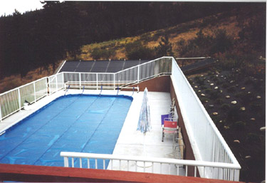
![]()
HOW DO SOLAR POOL HEATING
SYSTEMS WORK?
|
|
Adequate swimming pool heating can be achieved by having low temperature collectors directly connected to the filter circulation. In a few cases an additional booster pump or a slightly larger filtration pump may be needed. Today's most efficient systems employ the use of an automatically controlled diverting valve. The pool's filtration system is set to run during the period of most intense sunshine. During this period, when the solar control senses that adequate heat is present in the solar collectors, it causes a motorized diverting valve to turn, forcing the flow of pool water through the solar collectors, where water is heated. The heated water then returns to the pool. When heat is no longer present, the water bypasses the solar collector. Thus, most systems have very few moving parts which minimizes operation and maintenance requirements. Additional precautions are required against corrosion in collectors, since the water is quite aggressive (use of low temperature collectors, possibly made of plastics). |
PLACING THE SYSTEMS
Systems can quite easily be placed out of sight in a remote places, for
example upon a suitable roof; however some basic design rules should be
observed. The chosen site should be level or slightly sloping (less than 30
deg. to horizontal) with the return manifolds higher than the infeed manifolds
and all hoses rising steadily from one to the other to ensure all air is
expelled during operation.
Both a non-return valve and a vacuum release valve should be fitted to
systems placed at more than 1 meter above pool level to prevent the reverse
flow of water into the pool and the flattening of hoses when the collector
drains at the end of each operating cycle. All connections into the pool
filtration circuit must be made after the filter unit and, if applicable, before
any existing conventional heater to avoid pressurising the solar system.
OPERATION AND MAINTENANCE
The simplicity of solar pool heating systems means that operation and
maintenance requirements are minimal. In fact, in most cases no additional maintenance
beyond normal filter cleaning and winter close-up is necessary. The system
should be drained in the winter months; however, in some cases even this may
not be necessary because the system drains itself. In addition, solar pool
heating equipment is so reliable that many solar pool collector manufacturers
provide warranty coverage for their products which far exceeds that of
automobiles and household appliances.
SOLAR SPACE HEATING
So far only systems for warm water preparation have been described. An
active solar heating plant can provide hot water, and additional heating via
the central heating system at the same time. To get a reasonable output, the
central heating temperature must be as low as possible (preferably around 50
deg.C), and there must be a storage for the space heating. A smart solution is
to combine the solar heating installation with under-floor heating, where the
floor function as heat storage.
Solar heating installations for space heating usually give less profit than
hot-water installations, both according economy and energy, as heating is
seldom needed during summer. But if heat is needed during summer (like in some
mountain areas), then space heating installations is a good idea. In central
Europe, some 20% of the total heat load of a traditional house, and close to
50% low energy house, could be supplied by an advanced active solar heating
system employing water storage only. The remaining heat need to be drawn from
auxiliary energy systems. To increase the solar fraction, would in practice
require larger storage capacities.
For single houses, systems with well-insulated water tanks between 5-30 m³
have been constructed especially in Switzerland (so-called Jenni system) but
the costs are too high and the storage is often unpractical. The solar fraction
of a Jenni-system is >50% and may reach even 100%.
If all of the load in the above example were supplied by an up-to-date
active solar heating system, a 25 m² collector area and 85 m³ storage water
tank with 100 cm insulation around would be needed. Improving the energy
storage capacity of the storage unit, would dramatically improve the practical
possibilities for storage.
Although individual solar space heating is technically feasible, it is
likely that it would be far more cost effective to invest in insulation to cut
space heating demands.
![]()
SEASONAL STORAGE
If a far larger collector together with a much larger storage tank were
fitted, solar energy should be able to supply energy for several houses. Basic
problem with solar energy is related to the fact that most of the energy is
needed during the winter when solar insolation is the lowest and on the other
side much of summer potential output can not be used because the demand is
mostly not there. So capital investment into larger collectors with larger
gains would be wasted.
Despite this fact there are several installations using summer heat produced
by solar collectors and saved through to the winter. These installations are
using large storage tanks (seasonal storage). Problem is that the volume of hot
water storage needed to supply a house is almost the same size as the house
itself. In addition, the tank would need to be better insulated. A normal
domestic hot water cylinder would require insulation of 4 metres thick to
retain most of its heat from summer to winter. It therefore pays to make
storage volume really enormous. This reduces the ratio of surface area to
volume.
Large solar heating plants for district heating are now in use, e.g. in
Denmark, Sweden, Switzerland, France or USA. Solar modules are mostly installed
directly at the ground in larger fields. Without a storage such solar heating
installation would cover approximately 5% of the annual heat demand, as the
plant never must produce more than the minimum heat consumption, including loss
in the district heating system (by 20% transmission loss). If there is a
day-to-night storage, then the solar heating installation can cover 10-12% of
the heat demand including transmission loss, and with a seasonal storage up to
100%. There is also a possibility to combine district heating with individual
solar water collectors. Then the district heating system can be closed during
summer, when the sun provides hot water, and there is no need for space
heating.
PRESENT SOLAR STORAGE
SYSTEMS
Large-size seasonal storage systems for communities have been demonstrated
in several countries but are still too expensive. The size of a central storage
system may range from a few thousand m³ up to a few 100 000 m³. The largest
storage project in Europe is in Oulu, Finland where a large rock cavern heat
storage of 200 000 m³ will be connected to a combined heat and power plant
burning biomass. This district heating plant was built under the EU-Thermie
programme.
Another successful project with seasonal storage of hot water has been
constructed in Lyckebo, Sweden. This project is using a rock cavern filled with
water (volume of 105 000 m3) and flat plate solar collectors with area of 28
800 m2 which supply 100% energy (8500 MWh/a) for space and water heating of 550
dwellings. All houses are connected to communal district heating system. The
temperature of supply water is 70 degrees Celsius and the temperature of return
water is 55 degrees.
The pay-back times of such installations are very long. The important lesson
from space heating systems has been that it is essential to invest in energy
conservation and passive solar design first and then to use solar energy to
help supply the remaining reduced load.
COMBINING SOLAR WITH OTHER
RENEWABLE SOURCES
Combining renewable energy sources such as solar heat with solar storage in
form of biomass may be a good solution. Or, if the remaining load of a low
energy house is very low, some liquid or gaseous biofuels with advanced burners
together with solar heating may be used.
Solar heating together with solid biomass boilers may provide interesting
synergy and also solution to the seasonal storage of solar energy. Using
biomass in the summer may be non-optimal, as the boiler efficiencies at partial
loads are low and also relative piping losses may be high - in smaller systems
using wood in the summer may even be uncomfortable. Solar heating may well
provide 100% of the summertime loads in such cases. In the winter, when the
solar yield is negligible, the biomass options provides almost all of the heat
needed.
Experiences notably from central Europe with solar heating and biomass
together are positive. Some 20-30% of the total load is typically provided by
solar heating and the main load, i.e. 70-80% of the total load, by biomass.
Combined solar heat and biomass may be used for both single-family houses and
for district heating. For central European conditions, around 10 m³ of biomass
(e.g. wood) would be enough for a single-family house with solar heating system
replacing well up to 3 m³ per year in a household.
![]()
Solar Thermal Commercial Water
Heating
 Many businesses use solar water
heating to preheat the water before using another method to heat it to boiling or
for steam. Being less dependent on fluctuating fuel prices is another factor
that makes solar system a wise investment. In many cases installation of solar
water heating will derive an immediate and significant savings in energy costs.
Depending on the volume of hot water needed and the local climate a business
can realize savings of 40 - 80% on electric or fuel bills. For example the
24-story Kook Jae office building in Seoul, South Korea meets over 85% of its
daily hot water needs with a solar hot water heating system. The system has been
in operation since 1984 and is so efficient that it has exceeded it's design
specifications and even provides 10 to 20 percent of the annual space heating
requirement.
Many businesses use solar water
heating to preheat the water before using another method to heat it to boiling or
for steam. Being less dependent on fluctuating fuel prices is another factor
that makes solar system a wise investment. In many cases installation of solar
water heating will derive an immediate and significant savings in energy costs.
Depending on the volume of hot water needed and the local climate a business
can realize savings of 40 - 80% on electric or fuel bills. For example the
24-story Kook Jae office building in Seoul, South Korea meets over 85% of its
daily hot water needs with a solar hot water heating system. The system has been
in operation since 1984 and is so efficient that it has exceeded it's design
specifications and even provides 10 to 20 percent of the annual space heating
requirement.
Solar heating
at Kook Jae building.

There are several different configurations of solar water
heating systems. In general, however, the amount of hot water that a commercial
business demands requires an active system. Active systems typically consist of
solar collectors on a south-facing roof (in Northern hemisphere), and a storage
tank near the existing water collector. When sufficient heat is present in the solar
panel, a controller turns on a pump which begins circulating fluid, either
water or antifreeze, through the solar panel. The fluid picks up the heat from
the collector and transfers the heat to the potable water supply which is
stored in a tank until needed. If the solar-heated water is not at the desired
temperature, a back-up energy source can be used to bring the water temperature
up to the desired level. The type and size of a system is calculated by determining
water-heating load similar to the way described in chapter on solar collector
sizing for households (see above). Similarly required maintenance for
commercial systems will depend on the type and size of system, but the
simplicity of solar water heating systems means that maintenance is minimal.
While for many businesses the biggest advantage of a solar water collector
is the resulting savings in utility bills, value must be placed on the
substantial environmental benefit. Air pollutants, such as sulphur dioxides,
carbon monoxide and nitrous oxides are also displaced when a business owner
decides to tap into a cleaner source of energy - the sun.
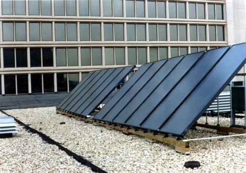
Industrial
Process Heat
Industry requires heat in a variety of temperature ranges, depending on the
process at hand. Many of these processes can be served by collectors ranging
from the flat-plate variety, which are restricted to temperatures below 100
degrees C, to concentrating collectors which can produce temperatures of
several hundred degrees.
SOLAR COOLING
The world demand of energy for air-conditioning and cooling is still
increasing. This is not only due to an increasing wish for comfort in highly
industrialized countries but also follows the necessity of e.g. food storage
and medical applications in hot climates especially third world countries.
Today there are mainly three techniques available for active cooling. First
of all the compression machine driven by electricity which is today the
standard cooling device in Europe. On the other hand there is the absorption
cooling machine using heat as driving force. Both compression and absorption
machines are able to provide air conditioning, i.e. chilled water at about 5°C,
and refrigeration, i.e. temperatures below 0°C. There is a third possibility
which is desiccant and evaporative cooling used for air conditioning. All
systems can be driven by solar energy and in addition have the advantage of
using absolute harmless working fluids like simple water, solutions of certain
salts in water or ammonia. Possible applications of this technology are not
only air-conditioning but also refrigeration (food storage etc.).
The vast use of present compression cooling machines is also responsible for
an increasing peak demand of electrical power in summer which reaches already
the capacity limit in some southern countries. Because most of the electrical
power stems from fossil fired power plants this also increases the production
of CO2 which is no longer acceptable. A more innovative approach is to use
solar energy from thermal collectors as driving force for air-conditioning
systems. This idea is very promising in the sense that to some extent the
demanded cooling power is correlated with the incident solar radiation
intensity which also delivers the driving force.
In principle compression cooling machine can be driven by solar energy i.e.
by electricity from photovoltaic panels but we will restrict to sorption
cooling machines using heat from a thermal solar collector due to the advantage
of using environmental harmless refrigerants and the higher market penetration
of thermal solar collectors. A higher market penetration is also found for
absorption cooling machines compared to desiccant cooling systems. Moreover
absorption machines can also be used as retrofit in standard air conditioning
systems using chilled water. Solar collectors are used for vaporization
heat in absorption machine.
In Kuwait, where air conditioning is essential for summer cooling in
residential, commercial and public buildings, the use of solar for air
conditioning has received serious attention during the seventies and eighties.
Development has primarily focused on modifying conventional steam-fired cooling
systems for use with solar-heated water at temperatures below 100°C. Some
attention has also been paid to using photovoltaic systems to generate the
electricity needed to operate a conventional vapour compression air
conditioning unit.
![]()
SOLAR DRYING
A solar collector that heats air, can be used as a cheap heat source for
drying crops like corn, fruit or vegetable. Since solar air collectors can
efficiently increase the ambient air temperature by 5 to 10 degrees Celsius
(some sophisticated devices by even more), it can also be used effectively for
air conditioning in warehouses.
The use of simple and low cost solar air collectors for heating the drying
air of crop dryers offers a promising alternative to reduce the tremendous post
harvest losses in developing countries. The lack of adequate storage and
preservation facilities in the developing countries result in considerable food
losses. Although reliable estimate of the magnitude of the post harvest losses
in these countries is not possible, some references indicates estimates of
about 50 to 60%. To avoid such losses, growers usually sell of their produce
immediately after harvest at low prices. Reduction in these losses through the
processing of fresh products into dried products would be of great significant
to growers and consumers alike. In several developing countries, open air sun
drying is the widely practiced method of food preservation. This involves
spreading the fresh material on the ground, on rocks, along the roadside, or on
the roofs. The advantage of this method lies in its simplicity and cheapness.
However, the quality of the final product is low due to long drying time, contamination
by dirt and dust, infestation by insects and degradation by overheating.
Furthermore, drying to a low moisture content is difficult resulting in
spoilage during subsequent storage. The introduction of solar dryers is an
appropriate technology that can help to improve the quality of the dried
products and to reduce the wastage.
Various types of small scale solar dryers were developed for drying small
amounts of agricultural products in developing countries. In the natural
convection dryers, the solar air heater is either incorporated into the dryer,
or the air heater is connected to a cabinet or chamber dryer. The solar
air-collector may consist of a black mat covered by a plastic plate. The air is
drawn through the mat, where it is heated, and thereafter blown through the
crops. These dryers can be used both in arid and humid regions for drying
fruits, vegetables and spices. Due to their enlarged capacity they are mainly
used on larger farms or by cooperatives for producing high quality products. Integrating
the solar air heater into the south oriented roof of the barn is common system
used in industrialized countries for drying hay.
Solar dryers are usually classified according to the mode of air flow into
natural convection and forced convection dryers. Natural convection dryers do
not require a fan to pump the air through the dryer. The low air flow rate and
the long drying time, however, result in low capacity and product quality.
Thus, this system is restricted to the processing of small quantities
agricultural surplus for family consumption. Where large quantities of fresh
produce are to be processed for the commercial market, forced convection dryers
should be used. One fundamental disadvantage of forced convection dryers lies
in their requirement of electrical power to run the fan. Since the rural or
remote areas of many developing countries are not connected to the national
electric grid, the use of these dryers is limited to electrified urban areas.
Even in the urban locales with grid-connected electricity, the service is
unreliable. In view of the prevailing economic difficulties in most of these
countries, this situation is not expected to change in the foreseenable future.
The application of photovoltaic to generate the electricity required by the fan
could boost the dissemination of solar dryers in the developing countries.
In developed countries the solar air heater usually consists of a black
absorber foil, a transparent plastic foil where the air is forced by a fan
between the space. To enlarge the collector area, the roof is extended
southward to the ground and the whole roof is used as collector. The solar
greenhouse dryer is used for drying medicinal and aromatic plants on large
farms. By using a photovoltaic driven blower, it can be secured that only when
the sun shines, air is blown in. Such installations are commonly used in summer
cottages in Denmark and Sweden, where they keep the houses dry most of the
year.
While solar drying has many advantages over sun drying, lack of control over
the weather is the main problem with both methods. In many regions weather is
not suitable for sun or solar drying because there are few consecutive days of
high temperatures and low humidity. It is likely that the food will sour or
mold before drying is completed.
![]()
SOLAR
COOKING
Successful solar cookers were first reported in Europe and India as early as
the 18th century. Solar cookers and ovens, absorb solar energy and convert it
to heat, which is captured inside an enclosed area. This absorbed heat is
used for cooking or baking various kinds of food. In solar cookers temperatures
as high as 200 degrees Celsius can be achieved.
Solar cookers come in may shapes and sizes. For example there are: box
ovens, concentrating-type or reflector cookers, solar steam cookers etc. This
list could go on forever. Designs vary, but all cookers trap heat in some form
of insulated compartment. In most of these designs the sun actually strikes the
food.
BOX-TYPE SOLAR COOKERS
Box-type solar cookers consist of a well-insulated box with a black
interior, into which black pots containing food are placed. The cover of the box
usually comprises a two-pane window that lets solar radiation enter the box
but keeps the heat from escaping. This in addition to a lid with a mirror on
the inside that can be adjusted to intensify the incident radiation when it is
open and improve the box's insulation when it is closed.
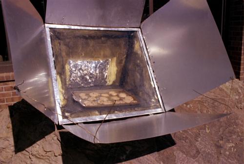
The main advantages of box-type solar cookers are:
![]() They make use of both direct
and diffuse solar radiation.
They make use of both direct
and diffuse solar radiation.
![]() Several vessels can be heated
at once.
Several vessels can be heated
at once.
![]() They are light and portable.
They are light and portable.
![]() They are easy to handle and
operate.
They are easy to handle and
operate.
![]() They needn't track the sun.
They needn't track the sun.
![]() The moderate temperatures make
stirring unnecessary.
The moderate temperatures make
stirring unnecessary.
![]() The food can be kept warm until
evening.
The food can be kept warm until
evening.
![]() The boxes are easy to make and
repair using locally available materials.
The boxes are easy to make and
repair using locally available materials.
![]() They are relatively inexpensive
(compared to other types of solar cookers).
They are relatively inexpensive
(compared to other types of solar cookers).
There are some disadvantages too:
![]() Cooking must be limited to the
daylight hours.
Cooking must be limited to the
daylight hours.
![]() The moderate temperatures make
for long cooking times.
The moderate temperatures make
for long cooking times.
![]() The glass cover causes
considerable heat losses.
The glass cover causes
considerable heat losses.
![]() Such cookers cannot be used for
frying or grilling.
Such cookers cannot be used for
frying or grilling.
Thanks to their simple construction, relatively low cost, uncomplicated handling and easy operation, solar cooking boxes are the most widely used type of solar cooker. There are all sorts of box-type solar cookers: mass-produced, hand-crafted, do-it-yourself types etc. with shapes resembling a suitcase or a wide, low box, and stationary types made of clay, with a horizontal lid for tropical and subtropical areas or an inclined lid for more temperate regions. Standard models with aperture areas of about 0,25 m2 are the rule for a family of five, and larger versions measuring 1 m2 and more are available on the market.
GUIDELINES FOR CONSTRUCTION
Since the heat absorbed by the inner box needs to be conducted to the area
beneath the cooking pots, the best choice of material is aluminium, because it
is a very good heat conductor. Additionally, aluminium is good for reasons of
corrosion prevention, i.e. iron sheet boxes, even galvanized ones, could not
stand up indefinitely to the hot, humid conditions that are created inside
during the cooking process. Sheet copper is prohibitively expensive.
No metal parts should placed to the outside around the top rim of the inner
box: thermal bridges must be avoided. The insulation may consist of glass, rock
wool or some natural material like residue from the processing of peanuts,
coconuts, rice, corn, etc. Whatever kind of material is used, it must be kept
dry.
The cover could consist of one or two panes of glass with a layer of air
between them. The pane-to-pane clearance usually amounts to 10...20 mm. Recent
experiments have shown that a honeycomb structure of transparent material that
divides the inner space into small vertical compartments can substantially
reduce the cooker's heat losses, thus increasing its efficiency accordingly.
The inside cover pane is exposed to substantial amounts of thermal stress, for
which reason tempered (safety) glass is frequently used; otherwise, both panes
may consist of normal window glass with a thickness of about 3 mm.
The outer cover, or lid, of the solar cooking box always serves as a
reflector to amplify the incident radiation. The reflecting surface may consist
of an ordinary glass mirror (heavy, expensive, fragile, but easily obtainable
anywhere), plastic sheet with a reflecting coating (Mylar, Tedlar, etc.; cheap,
but not very durable and hard to find), or a metal mirror (unbreakable). In an
emergency, even foil from empty cigarette packs will do the job.
The outer box of the solar cooker may be made of wood, glass-reinforced
plastic (GRP) or metal. GRP is light, inexpensive and fairly weather-resistant,
but not necessarily stable enough for continuous use. Wood is more stable, but
also heavier and less weather-resistant. A metal case aluminium with wooden
bracing offers the best finish and is adequately stable with regard to
mechanical impact and the effects of weather. An aluminium-clad wooden box is the
most stable of all, but it is expensive and time-consuming to make, in addition
to being heavy.
The capacity of a normal box-type solar cooker with a 0.25 m2 area of
incidence (aperture) amounts about 4 kg ready-to-eat food, or enough to feed a
family of five.
The inside of a solar cooking box can reach a peak temperature of over
150 deg.C on a sunny day in the tropics; that amounts to a thermal head of 120
deg.C, referred to the ambient temperature. Since the water content of food
does not heat up beyond 100 deg. C, a loaded solar cooker will always show an
accordingly lower inside temperature. The temperature inside of the solar
cooker drops off sharply when the vessels are placed inside it. Also important
is the fact that the temperature remains well below 100 deg.C for the greater
part of the cooking time. Nevertheless the boiling temperature of 100 deg. C is
not necessary for most vegetables and cereals.
The average achievable cooking times in box-type solar cookers amount to
somewhere between 1 and 3 hours for good insolation and a reasonable fill
volume. Thin-walled aluminium vessels yield much shorter cooking times than
stainless steel pots.
The time taken for cooking is also influenced by the following factors:
![]() The cooking time is shortened
by strong insolation and viceversa
The cooking time is shortened
by strong insolation and viceversa
![]() High ambient temperatures
shorten the cooking time, and viceversa
High ambient temperatures
shorten the cooking time, and viceversa
![]() Small volumes (shallow fill) in
the pot make for shorter cooking times, and vice versa.
Small volumes (shallow fill) in
the pot make for shorter cooking times, and vice versa.
![]()
REFLECTOR COOKERS
The most elementary kind of reflector cooker is one that consists of (more or
less) parabolic reflectors and a holder for the cooking pot situated at the
cooker's focal spot. If the cooker is properly aligned with the sun, the solar
energy bounces off of the reflectors such that it all meets at the focal spot,
thus heating the pot. The reflector can be a rigid axial paraboloid, made for
example from sheet metal or from a reflecting foil. The reflecting surface is
usually made of treated aluminium or a mirror-finish metal or plastic sheet,
but it may also consist of numerous little flat mirrors cemented onto the
inside of the paraboloid. Depending on the desired focal length, the reflector may
have the shape of a deep bowl that completely swallows the pot (short focal
length, pot shielded from the wind) or that of a shallow plate with the cooking
pot mounted in the focal point a certain distance above or in front of it.
All reflector cookers exploit only direct insolation and must track the sun
at all times. The tracking requirement makes them somewhat complicated to
handle, depending on the nature and stability of the stand and adjusting
mechanism.
 The advantages of
reflector cookers include:
The advantages of
reflector cookers include:
![]() The ability to achieve high
temperatures and accordingly short cooking times.
The ability to achieve high
temperatures and accordingly short cooking times.
![]() Relatively inexpensive versions
are possible.
Relatively inexpensive versions
are possible.
![]() Some of them can also be used
for baking.
Some of them can also be used
for baking.
The above mentioned merits stand in contrast to the following drawbacks,
some of which are quite serious:
![]() Depending on its focal length,
the cooker must be realigned with the sun every 15 minutes or so.
Depending on its focal length,
the cooker must be realigned with the sun every 15 minutes or so.
![]() Only direct insolation is
exploited, i.e. diffuse radiation goes unused.
Only direct insolation is
exploited, i.e. diffuse radiation goes unused.
![]() Even scattered clouds can cause
high heat losses.
Even scattered clouds can cause
high heat losses.
![]() The handling and operation of
such cookers is not easy; it requires practice, a good grasp of the working
principle.
The handling and operation of
such cookers is not easy; it requires practice, a good grasp of the working
principle.
![]() The reflected radiation is
blinding, and there is danger of injury by burning when manipulating the pot in
the cooker's focal spot.
The reflected radiation is
blinding, and there is danger of injury by burning when manipulating the pot in
the cooker's focal spot.
![]() Cooking is restricted to the
daylight hours.
Cooking is restricted to the
daylight hours.
![]() The cook must stand out in the hot
sun (single exception: fixed-focus cookers).
The cook must stand out in the hot
sun (single exception: fixed-focus cookers).
![]() The efficiency is heavily
dependent on the momentary wind conditions.
The efficiency is heavily
dependent on the momentary wind conditions.
![]() Any food cooked around noon or
in the afternoon gets cold by evening.
Any food cooked around noon or
in the afternoon gets cold by evening.
Particularly the cooker's complicated handling, in combination with the fact that the cook has to stand out in the sun, is a major impediment with regard to the acceptance of reflector cookers. But in China, where the food demands high cooking power and temperature, eccentric axis reflector cookers have been disseminated and accepted in a large number.
THERMAL OUTPUT
The thermal output of a solar cooker is determined by the insolation level,
the cooker's effective collecting area (usually between 0.25 m2 and 2 m2), and
its thermal efficiency (usually between 20% and 50%). Table below compares some
typical area, efficiency and cooking-power values for a box-type solar cooker
and a reflector.
Standard values for area,
efficiency and power output of reflector cookers and cooking boxes
|
|
Area in m2 |
Normal efficiency |
Output in W at insolation of 850 W/m2 |
Time needed to cook 1 litre of water |
|
Reflector cooker |
1,25 |
30 % |
320 |
17 min. |
|
Cooking box |
0,25 |
40 % |
85 |
64 min. |
![]()
As a rule, reflector cookers have a much larger collecting area than do
cooking boxes. Consequently, they are able to generate a much higher power
output, meaning that they can boil more water, cook more food, or process
comparable amounts in less time. On the other hand, their thermal efficiency is
lower, because the cooking pot is completely exposed to the cooling effects of
the surrounding atmosphere.
In many tropical and subtropical countries, one can count on clear skies and
normal daily insolation patterns for most of the year. At about midday, when
the global radiation reaches up to 1000 W/m2 , the thermal output levels (50 to
350 W, depending on the type and size of the cooker) may be regarded as quite
realistic. The insolation is naturally lower during the morning and afternoon
hours and cannot be fully compensated for by solar tracking.
By way of comparison: burning 1 kg of dry wood in one hour yields
approximately 5000 W times the thermal efficiency of the cooking facility (15%
for a three-stone hearth and 25-30% for an improved cookstove used in
developing countries). The thermal power actually reaching the cooking pot
therefore amounts to between 750 and 1500 W.
Insolation drops off sharply under cloud and during the rainy season. The
lack of direct radiation leaves reflector cookers without the slightest chance,
and cooking boxes can do little more than keep prepared food warm. The weak
point of solar cooking is that no matter what kind of device is used: on cloudy
and rainy days (up to between 2 and 4 months per year in most Third World
countries) cooking has to be done according to conventional methods, e.g. over
a wood/dung fire or on a gas/kerosene-fuelled cooker.
SOLAR RADIATION
The first and foremost prerequisite for success in a solar cooker
application is adequate insolation, with only infrequent interruptions during
the day and/or the year. The duration and intensity of solar radiation must
suffice to allow the use of a solar cooker for prolonged, worthwhile regular
periods. While cooking with solar energy is possible in Central Europe on a
sunny summer day, a minimum irradiation of 1500 kWh/m2 per year (corresponding
to a mean daily insolation of 4 kWh/m2 per day) should be available for any
solar cooker. But these annual data can sometimes be misleading. The essential condition
for solar cooking is a reliable summer weather, i.e. essentially predictable
sequences of regular cloudless days.
Supply of solar energy varies substantially from country to country, even
within the Third World's tropical belt. Thus, local data must be referred to -
and they are not always available. Some examples: In India solar radiation in
most regions is good to very good for purposes of solar energy exploitation.
The yearly averages of daily annual global radiation range from 5 to 7 kWh/m2
per day, depending on the region. In most places, the insolation reaches its
minimum during the monsoon season and is nearly as weak again during the months
of December and January.
In Kenya's climate and insolation potential are favourable to the use of
solar cookers. Kenya is close to the equator and therefore has a purely
tropical climate. In Nairobi, the daily irradiation alternates between 3.5
kWh/m2 per day in July and 6.5 kWh/m2 per day in February, but it remains
practically uniform (6.0...6.5 kWh/m2 per day) in other regions of Kenya like
Lodwar. Solar irradiation in Nairobi is adequate for cooking with solar energy
nine months a year (excluding June through August). On the other hand,
conventional cooking facilities must be relied on for cloudy or hazy days. In
the Lodwar area, though, solar cookers can be used year-round.
SOLAR COOKERS FOR DEVELOPING
COUNTRIES
The purpose of solar cookers, of course, is to save energy in the face of a
double energy crisis: the poor people's energy crisis is the increasing
scarcity of firewood, and the nation's energy crisis is the growing pressure on
its balance of payments. Solar cooker should be judged with that in mind.
Compared to other nations, developing countries consume very little energy.
For example, India's 1982 per capita energy consumption rate, at 7325 GJ, was
one of the world's lowest. But the country's energy consumption rate is
increasing nearly twice as fast as its gross national product. The same is true
for the most developing countries.
The poor majority of the people in developing countries cover most of their
energy requirement in a non-commercial way, using traditional, locally
available sources of energy and their own physical labour. They simply cannot
afford to buy any appreciable amounts of commercial energy.
The logical consequence is a relative shortage of fuel for use by the poor,
whose living conditions deteriorate even more as a result. Solar cookers could
at least try to compensate.
If the poor majority of the Third World's people is the target group, then
solar cookers must be first and foremost to the benefit of the rural population.
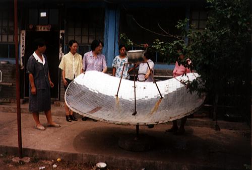
![]()
COOKING-ENERGY QUANTITIES
The daily fuel requirement varies according to the kind of food being cooked
and the number of warm meals. In the typical developing country, each native
burns one ton of firewood each year.
In India, the average family needs somewhere between 3 and 7 kg of wood per
day; in the cooler regions, the daily firewood demand varies between just under
20 kg in the winter and 14 kg in the summer. In the southern part of Mali, the
average 15-member (!) family burns about 15 kg of wood each day. A survey
conducted in an Afghan refugee camp in Pakistan showed a daily firewood demand
of up to 10 kg per family and day. More than half of the wood used in the
average household goes for baking, and the remainder is used for cooking.
Additional wood is needed for heating in the wintertime, of course.
Despite the fact that above examples indicate that the required amounts of
cooking energy are extremely variable much cooking energy can be saved by using
solar cookers.
The prime function of solar cookers is to help reduce firewood consumption,
since most cooking fires are still fuelled with firewood. The trouble is,
firewood is usually quite inexpensive in comparison with kerosene, bottled gas
or electricity (based on relative energy content).Increasing, uncontrolled
felling of wood for people's own use and for selling are a main cause of
deforestation, desertification, erosion, receding groundwater levels and it has
long-term adverse effects on the ecological balance. Pakistan's meager forest
heritage and rampant deforestation in Kenya show that such fears are
well-founded. If denudation of the Sudan's forests continues at the present
rate, they will be gone by the year 2005.
For most solar cookers, little data is available on the actual cost of
production. Since most of those solar cookers are prototypes that do not yet
display the technical maturity needed for series production, pertinent
information is of low indicative value. Due to the chronic shortage of foreign
currency in the Third World, preference should be given to cookers that can be
made locally using indigenous materials.
The problem is that practically any amount of money paid for solar cooker,
however small, would still be too expensive for most rural households as long
as firewood can be gathered for free and the farmers earn very little money.
On the whole, solar cookers could, at best contribute little toward a
national energy policy. But they could make a very substantial contribution
toward improving the living conditions of the poor and helping them overcome
their own energy crisis.
SOLAR WATER DISTILLATION
Many people throughout the world do not have access to clean water. Of the
2.4 billion people in developing countries, less than 500 million have access
to safe drinking water, let alone distilled water. The answer to these problems
is a solar still. A solar still is a simple device that can convert saline,
brackish, or polluted water into distilled water. The principles of solar
distillation have been around for centuries. In the fourth century B.C.,
Aristotle suggested a method of evaporating sea water to produce potable water.
However, the first solar still was not produced until 1874, when J. Harding and
C. Wilson built a still in Chile to provide fresh water to a nitrate mining
community. This 4700 m2 still produced 24000 litres of water per day. Currently
there are large still installations in Australia, Greece, Spain and Tunisia,
and on Petit St. Vincent Island in the Caribbean. Smaller stills are commonly
used in other countries.
Practically any seacoast and many desert areas can be made inhabitable by
using sunshine to pump and purify water. Solar energy does the pumping (see
chapter on photovoltaics), purification, and controls seawater feed to
the stills.
![]()
SOLAR STILL BASICS
The most common still in use is the single basin solar still. The still consists
of an air tight basin that holds the polluted or salt water, covered by a
sloped sheet of glass or plastic. The bottom of the basin is black to help
absorb the solar radiation. The cover allows the radiation to enter the still
and evaporate the water. The water then condenses on the under side of the
cover (which is cooled by the outside air), and runs down the sloped cover into
a trough or tube. The tube is also inclined so that the collected water flows
out of the still.
The process is exactly Mother Nature's method of getting fresh water into
the clouds from oceans, lakes, swamps, etc. All the water we have ever consumed
has already been solar distilled a several thousand times around the hydrologic
cycle.

SOLAR STILL PERFORMANCE
Operation of the still requires no routine maintenance and has no routine
operating costs. The rated production of the still is an estimated annual average
and is not exact, as the amount of sunshine can vary widely. Stills produce
more in hot climates than in cold ones, more at low latitudes than high, and
more in summer than in winter. At the 23° North latitude of the central
Bahamas, the estimated average production of the installation was 12 times
higher in June than in mid-winter. In higher latitudes, addition of a mirror to
the rear of each still increases winter production. Some stills also functions
in freezing climates. In general solar still can produce 1 litre of distilled
of water a day per square meter of still. On very sunny days over one litre of
water can be gained. The still is usually filled once daily, at night or in the
morning.
STILL COSTS
The cost of a solar distillation system will vary widely, due to size and
site-specific circumstances. The stills are usually inexpensive to build. Some
small models designed in the USA cost 25 USD with glass or 18 USD with plastic
(the amount of water produced is smaller). If the stills are used for one year,
they will produce water at approximately 10 cents per litre.
WATER QUALITY
The distilled water produced is of very high quality, normally better than
that sold in bottles as distilled water. It routinely tests lower than one part
per million total dissolved solids. It is also aerated, as it condenses in the
presence of air inside the still. The water may taste a little strange at first
because distilled water does not have any of the minerals which most people are
accustomed to drinking. Tests have shown that the stills eliminated all
bacteria, and that the incidence of pesticides, fertilizers and solvents is
reduced by 7599,5%. This is of great importance for many countries where
cholera and other water borne diseases are killing people daily.
DESIGNING SOLAR STILL
There are a few things to keep in mind when designing the solar still:
![]() The tank can be made of cement,
adobe, plastic, tile, or any other water resistant material.
The tank can be made of cement,
adobe, plastic, tile, or any other water resistant material.
![]() If plastic is used to line the
bottom of the still or for the condensate trough, make sure the tank never
remains dry. This could melt the plastic.
If plastic is used to line the
bottom of the still or for the condensate trough, make sure the tank never
remains dry. This could melt the plastic.
![]() Insulation should be used if
possible. Even a small amount will greatly increase the efficiency of the
still.
Insulation should be used if
possible. Even a small amount will greatly increase the efficiency of the
still.
![]() The container holding the
distilled water should be protected from solar radiation to avoid
re-evaporation.
The container holding the
distilled water should be protected from solar radiation to avoid
re-evaporation.
![]()
SOLAR THERMAL POWER PRODUCTION
In addition to using the warmth of the sun directly, it is possible (in
areas with high level of solar radiation) to use the heat to make steam to
drive a turbine and produce electricity. If undertaken on a large scale, solar
thermal electricity is very cost-competitive. The first commercial applications
of this technology appeared in the early 1980's, and the industry grew very
rapidly. Today, utilities in the U.S. have installed more than 400 megawatts of
solar thermal generating capacity, providing electricity to 350,000 people and displace
the equivalent of 2,3 million barrels of oil annually. Nine plants in
California's Mojave Desert are generating 354 MWe of solar electric capacity,
and have accumulated 100 plant-years of commercial operating experience.
The technology is maturing to the point where officials say it can compete
directly with conventional power technologies in many regions of USA. A number
of opportunities for solar thermal projects may open soon in other regions of
the world. India, Egypt, Morocco, and Mexico have active programs that will
receive grants from the Global Environment Facility, and independent power
producers are designing power projects in Greece, Spain, and the US.
According to the way how the heat is produced solar thermal power plants can
be divided between solar concentrators (mirrors) and solar ponds.
SOLAR CONCENTRATORS
Solar thermal electric power plants generate heat by using lenses and
reflectors to concentrate the sun's energy. Because the heat can be stored, these
plants can generate power when it is needed, day or night, rain or shine.
Large mirrors - of the point focusing type or the line focusing variety -
can concentrate solar beams to such an extent that water can be converted to
steam with enough power to drive a generating turbine. Enormous fields of such
mirrors have been constructed by Luz Corp. in the Californian desert, for the
production of 354 MW of electric power. Such systems can convert solar to
electric power with an efficiency of about 15%.
All solar thermal technologies except solar ponds achieve high temperatures
by utilizing solar concentrators to reflect sunlight from a large area to a
smaller receiver area. A typical system consists of the concentrator, receiver,
heat transfer, storage system and a delivery system.
The sun's heat can be collected in a variety of different ways. Todays
technology includes solar parabolic troughs, solar parabolic dish and power
towers. Because these technologies involve a thermal intermediary, they can be
readily hybridized with fossil fuel and in some cases adapted to utilize
thermal storage. The primary advantage of hybridization and thermal storage is
that the technologies can provide dispatchable power (dispatchability means
that power production can be shifted to the period when it is needed) and
operate during periods when solar energy is not available. Hybridization and
thermal storage can enhance the economic value of the electricity produced and
reduce its average cost.
Solar Parabolic Troughs
|
|
These systems use parabolic trough-shaped mirrors to focus sunlight on thermally efficient receiver tubes that contain a heat transfer fluid. Fluid is heated to almost 400 deg.C and pumped through a series of heat exchangers to produce superheated steam which powers a conventional turbine generator to produce electricity. A transparent glass tube placed in focal line of the trough may envelop the receiver tube to reduce heat loss. Parabolic troughs usually employ single-axis or dual-axis tracking. In rare instances, they may be stationary. |
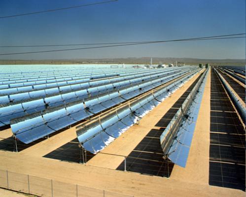
Nine trough systems, built in the mid to late 1980's by Luz International set up electricity-generating plants in the southern California desert with a total installed capacity of 354 MW, making parabolic troughs the largest solar thermal electric generating producers to date. These plants supply electricity to the Southern California Edison utility grid. In 1984 Luz International installed Solar Electric Generating System I (SEGS I) in Daggett, California. It has an electricity capacity of 13,8 MW. Oil is heated in the receiver tubes to 343°C to produce steam for electricity generation. SEGS I contains six hours of thermal storage, and uses natural gas-fueled super heaters to supplement the solar energy when solar energy is not available. Luz also constructed additional plants, SEGS II through VII, with 30 MW capacity each. In 1990, Luz completed construction of SEGS VIII and IX in Harper Lake, each with 80 MW capacity. As a result of numerous regulatory and policy obstacles, Luz International and four subsidiaries filed for bankruptcy on November 25, 1991. Three companies now operate and maintain SEGS I - IX under the same contract that Luz International had negotiated with Southern California Edison. Plans to construct SEGS X, XI, and XII were canceled, eliminating 240 MW of additional planned capacity.
|
|
Cost projections for trough technology are higher than those for power towers and dish/engine systems (see bellow) due in large part to the lower solar concentration and hence lower temperatures and efficiency. However, with long operating experience, continued technology improvements, and operating and maintenance cost reductions, troughs are the least expensive, most reliable solar thermal power production technology for near-term applications. |
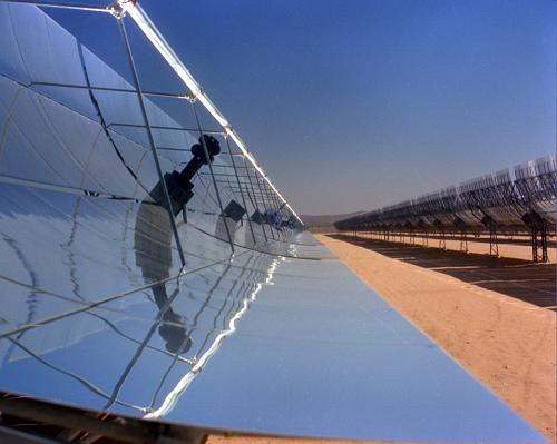
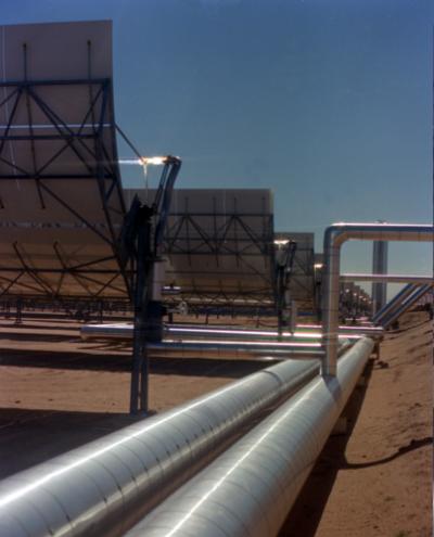
![]()
Solar Parabolic
Dish/engine 
|
|
These systems use an array of parabolic dish-shaped mirrors (similar in shape to a satellite dish) to focus solar energy onto a receiver located at the focal point of the dish. Fluid in the receiver is heated up to 1000°C and is utilized directly to generate electricity in a small engine attached to the receiver.Engines currently under consideration include Stirling and Brayton cycle engines. Several prototype dish/engine systems, ranging in size from 7 to 25 kW have been deployed in various locations in the USA. High optical efficiency and low start up losses make dish/engine systems the most efficient of all solar technologies. A Stirling engine/parabolic dish system holds the world's record for converting sunlight into electricity. In 1984, a 29% net efficiency was measured at Rancho Mirage, California. |
|
|
In addition, the modular design of dish/engine systems
make them a good match for both remote power needs in the kilowatt range as well
as hybrid end-of-the-line grid-connected utility applications in the megawatt
range. |
One such application was the STEP project in the state of Georgia (USA). The Solar Total Energy Project (STEP) was a large solar parabolic dish system that operated between 1982 and 1989 in Shenandoah, Georgia. It consisted of 114 dishes, each 7 meters in diameter. The system furnished high-pressure steam for electricity generation, medium-pressure steam for knitwear pressing, and low-pressure steam to run the air conditioning system for a nearby knitwear factory. In October 1989, Georgia Power shut down the facility due to the failure of its main turbine, and lack of funds for necessary plant repairs.
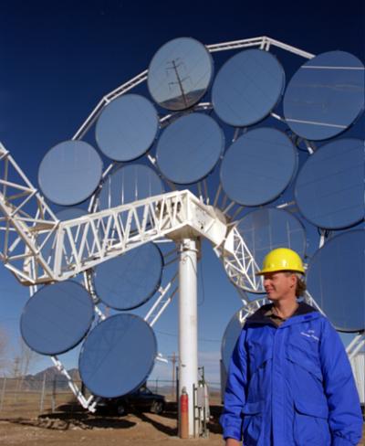
A cooperative venture between Sandia National Lab and
Cummins Power Generation is recently attempting to commercialize 7.5
kilowatt (kW) dish/engine systems. The systems are out of the component stage
and into the validation stage. When they accumulate sufficient running time,
they will be ready for the marketplace. Cummins hopes to sell 10,000 units a
year by 2004. Other companies are also entering into parabolic dish/Stirling
technology. Stirling Technology, Stirling Thermal Motors, and Detroit Diesel
have teamed up with Science Applications International Corporation in a $36
million joint venture with the Department of Energy, to develop a 25 kW
membrane dish/Stirling system.
The National Renewable Energy Laboratory (NREL) and the Cummins Engine
Company are testing two new receivers for dish/engine solar thermal power
systems: the pool-boiler receiver and the heat-pipe receiver. The pool-boiler
receiver operates like a double boiler on a stove. It boils a liquid metal and
transfers the heat energy to an engine on top. The heat-pipe receiver also uses
a liquid metal, but instead of pooling the liquid, it uses a wick to transfer
the molten liquid to a dome receiver.
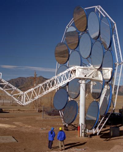
Solar
Central Receivers or Power Towers
|
|
These systems use a circular field array of heliostats (large individually-tracking mirrors) to focus sunlight onto a central receiver mounted on top of a tower which absorbs the heat energy that is then utilized in driving a turbine electric generator. A computer-controlled, dual-axis tracking system keeps the heliostats properly aligned, so that the reflected rays of the sun are always aimed at the receiver. Fluid circulating through the receiver transports heat to a thermal storage system, which can turn a turbine to generate electricity or provide heat directly for industrial applications. Temperatures achieved at the receiver range from 538°C to 1482°C. |
The first power tower Solar One built near Barstow in Southern California, successfully demonstrated this technology for electricity generation. This facility operated in the mid-1980's, used a water/steam system to generate 10 MW of power. In 1992, a consortium of U.S. utilities decided to retrofit Solar One to demonstrate a molten-salt receiver and thermal storage system. The addition of this thermal storage capability makes power towers unique among solar technologies by promising dispatchable power at load factors of up to 65%. In this system, molten-salt is pumped from a cold tank at 288 deg.C and cycled through the receiver where it is heated to 565 deg.C and returned to a hot tank. The hot salt can then be used to generate electricity when needed. Current designs allow storage ranging from 3 to 13 hours.
|
|
Solar Two, a power tower electricity generating plant in California, is a 10-megawatt prototype for large-scale commercial power plants. This facility first generated power in April 1996, and is scheduled to run for a 3-year test, evaluation, and power production phase to prove the molten-salt technology. It stores the sun's energy in molten salt at 550 deg.C, which allows the plant to generate power day and night, rain or shine. The successful completion of Solar Two should facilitate the early commercial deployment of power towers in the 30 to 200 MW range (source: Southern California Edison). |
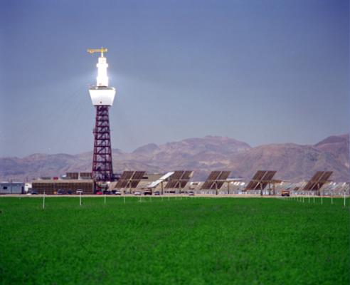

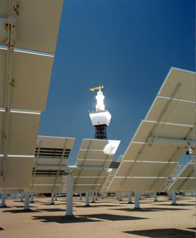
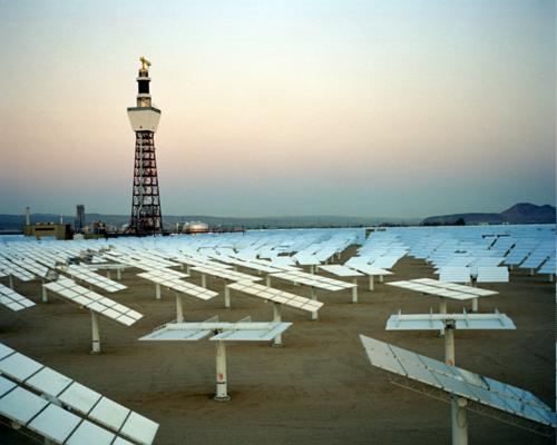
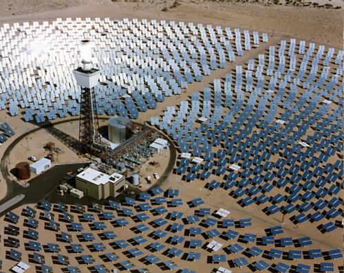
![]()
Technology Comparison
|
|
Table below highlights the key features of the three solar technologies. Towers and troughs are best suited for large, grid-connected power projects in the 30-200 MW size, whereas, dish/engine systems are modular and can be used in single dish applications or grouped in dish farms to create larger multi-megawatt projects. Parabolic trough plants are the most mature solar power technology available today and the technology most likely to be used for near-term deployments. Power towers, with low cost and efficient thermal storage, promise to offer dispatchable, high capacity factor, solar-only power plants in the near future. The modular nature of dishes will allow them to be used in smaller, high-value applications. Towers and dishes offer the opportunity to achieve higher solar-to-electric efficiencies and lower cost than parabolic trough plants, but uncertainty remains as to whether these technologies can achieve the necessary capital cost reductions and availability improvements. Parabolic troughs are currently a proven technology primarily waiting for an opportunity to be developed. Power towers require the operability and maintainability of the molten-salt technology to be demonstrated and the development of low cost heliostats. Dish/engine systems require the development of at least one commercial engine and the development of a low cost concentrator. |
Characteristics
of solar thermal electric power systems (as of 1993).
|
|
Parabolic Trough |
Dish/Engine |
Power Tower |
|
Size |
30-320 MW |
5-25 kW |
10-200 MW |
|
Operating Temperature (ºC/ºF) |
390/734 |
750/1382 |
565/1049 |
|
Annual Capacity Factor |
23-50 % |
25 % |
20-77 % |
|
Peak Efficiency |
20%(d) |
29.4%(d) |
23%(p) |
|
Net Annual Efficiency |
11(d)-16% |
12-25%(p) |
7(d)-20% |
|
Commercial Status |
Commercially Scale-up Prototype |
Demonstration |
AvailableDemonstration |
|
Technology Development Risk |
Low |
High |
Medium |
|
Storage Available |
Limited |
Battery |
Yes |
|
Hybrid Designs |
Yes |
Yes |
Yes |
|
Cost USD/W |
2,7-4,0 |
1,3-12,6 |
2,5-4,4 |
(p) = predicted; (d) = demonstrated;
Comparison of Major Solar
Thermal Technologies.
|
|
Parabolic Trough |
Parabolic Dish |
Power Tower |
|
Applications |
Grid-connected electric plants; process heat for industrial use. |
Stand-alone small power systems; grid support |
Grid-connected electric plants; process heat for industrial use. |
|
Advantages |
Dispatchable peaking electricity; commercially available with 4,500 GWh operating experience; hybrid (solar/fossil) operation. |
Dispatchable electricity, high conversion efficiencies; modularity; hybrid (solar/fossil) operation. |
Dispatchable base load electricity; high conversion efficiencies; energy storage; hybrid (solar/fossil) operation. |

Solar
Thermal Power Cost and Development Issues
The cost of electricity from solar thermal power systems depends on a
multitude of factors. These factors include capital and operating and
maintenance cost, and system performance. However, it is important to note that
the technology cost and the eventual cost of electricity generated is
significantly influenced by factors external to the technology itself. As an
example, for troughs and power towers, small stand-alone projects will be very
expensive. In order to reduce the technology costs to compete with current
fossil technologies, it will be necessary to scale-up projects to larger plant
sizes and to develop solar power parks where multiple projects are built at the
same site in a time phased succession. In addition, since these technologies in
essence replace conventional fuel with capital equipment, the cost of capital
and taxation issues related to capital intensive technologies will have a
strong effect on their competitiveness.

COST VERSUS
VALUE
Through the use of thermal storage and hybridization, solar thermal electric
technologies can provide a firm and dispatchable source of power. Firm implies
that the power source has a high reliability and will be able to produce power
when the utility needs it. As a result, firm dispatchable power is of value to a
utility because it offsets the utility's need to build and operate new power
plants. Dispatchability implies that power production can be shifted to the
period when it is needed. This means that even though a solar thermal
plant might cost more, it can have a higher value.
BENEFITS
Solar thermal power plants create two and one-half times as many skilled,
high paying jobs as do conventional power plants that use fossil fuels.
California Energy Commission study shows that even with existing tax
credits, a solar thermal electric plant pays about 1,7 times more in federal,
state, and local taxes than an equivalent natural gas combined cycle plant. If
the plants paid the same level of taxes, their cost of electricity would be
roughly the same.
![]()
POTENTIAL
Utilizing only 1% of the earth's deserts to produce clean solar thermal electric
energy would provide more electricity than is currently being produced on the
entire planet by fossil fuels.
FUTURE
Over 700 megawatts of solar thermal electric systems should be deployed by
the year 2003 in the U.S. and internationally. The market for these systems
should exceed 5,000 megawatts by 2010, enough to serve the residential needs of
7 million people which will save the energy equivalent of 46 million barrels of
oil per year.
SUMMARY
Solar thermal power technologies based on concentrating technologies are in
different stages of development. Trough technology is commercially available
today, with 354 MW currently operating in the Mojave Desert in California.
Power towers are in the demonstration phase, with the 10 MW Solar Two pilot
plant located in Barstow (USA), currently undergoing testing and power
production. Dish/engine technology has been demonstrated. Several system
designs are under engineering development, a 25 kW prototype unit is on display
in Golden (USA), and five to eight second-generation systems have been
scheduled for field validation in 1998. Solar thermal power technologies have
distinct features that make them attractive energy options in the expanding
renewable energy market world-wide.
Solar thermal electricity generating systems have come a long way over the
past few decades. Increased research and development of solar thermal
technology will make these systems more cost competitive with fossil fuels,
increase their reliability, and become a serious alternative for meeting or
supplying increased electricity demand.
Solar Ponds
Neither focusing mirrors nor solar cells can generate electricity at night.
For this purpose the daytime solar energy must be stored in storage tanks, a
process which occurs naturally in a solar pond.
Salt-gradient solar ponds have a high concentration of salt near the bottom,
a non-convecting salt gradient middle layer (with salt concentration increasing
with depth), and a surface convecting layer with low salt concentration.
Sunlight strikes the pond surface and is trapped in the bottom layer because of
its high salt concentration. The highly saline water, heated by the solar
energy absorbed in the pond floor, can not rise owing to its great density. It
simply sits at the pond bottom heating up until it almost boils (while the
surface layers of water stay relatively cool)! This hot brine can then be used
as a day or night heat source from which a special organic-fluid turbine can
generate electricity. The middle gradient layer in solar pond acts as an
insulator, preventing convection and heat loss to the surface. Temperature
differences between the bottom an surface layers are sufficient to drive a
generator. A transfer fluid piped through the bottom layer carries heat away
for direct end-use application. The heat may also be part of a closed-loop
Rankine cycle system that turns a turbine to generate electricity.
|
|
1. High salt concentration |
This type of power station has been tested at Beit Ha'Arava (Israel) near the Dead Sea. Israel leads the world in salt-gradient solar pond technology. Ormat Systems Inc. has installed several systems in the Dead Sea. The largest is a 5 MW electric system. This 20 hectare pond converts sunlight to electricity at an efficiency of about 1%. It consists of a pond of water with very high salinity in its lower depths. Although the solar pond operated successfully for several years, in 1989 it was shut down for economical reasons. The largest solar pond in the USA is a 0,3 hectare pond in El Paso, Texas, which has operated reliably since its start in 1986. The pond runs a 70 kW (electric) organic Rankine-cycle turbine generator, and a 20 000 litres per day desalting unit, while also providing process heat to an adjacent food processing company. The pond has reached and sustained temperatures higher than 90 deg. C in its heat-storage zone, generated more than 100 kW of electric power during peak output , and produced more than 350 000 litres of potable water in a 24 hour period. During five year operation, it has produced more than 50 000 kWh of electricity. A man-made, salt-gradient solar pond was built in Miamisburg, (Ohio, USA) and it heats a municipal swimming pool and a recreational building.

PHOTOVOLTAICS
Photovoltaics (PV) is the term derived from Greek word for light - photos-
and the name for unit of electromotive force - volt. Photovoltaics means direct
generation of electricity from light. Recently this process is utilised by means
of solar cells. The solar cells, made from semiconductor materials such as
silicon, produce electric currents when exposed to sunlight. By manufacturing
modules which contain dozens of such solar cells and connecting the modules
large power stations can be built. The largest photovoltaic power station that
has yet been constructed is the 5 MW system at Carrisa Plain, California. The efficiency
of photovoltaic power stations is presently about 10% but individual solar
cells have been fabricated with efficiencies exceeding 20%.
![]()
HISTORY OF PHOTOVOLTAICS
The history of photovoltaics dates back to 1839 and major developments
evolved as follows:
![]() In 1839 Edmund Becquerel, a
French physicist observed the photovoltaic effect.
In 1839 Edmund Becquerel, a
French physicist observed the photovoltaic effect.
![]() In 1883 Selenium PV cells were
built by Charles Edgar Fritts, a New York electrician. Cells converted light in
the visible spectrum into electricity and were 1% to 2% efficient. (light
sensors for cameras are still made from selenium today).
In 1883 Selenium PV cells were
built by Charles Edgar Fritts, a New York electrician. Cells converted light in
the visible spectrum into electricity and were 1% to 2% efficient. (light
sensors for cameras are still made from selenium today).
![]() In the early 1950's the
Czochralski meter was developed for producing highly purecrystalline silicon.
In the early 1950's the
Czochralski meter was developed for producing highly purecrystalline silicon.
![]() In 1954 Bell Telephone
Laboratories produced a silicon PV cell with a 4% efficiency and later achieved
11% efficiency.
In 1954 Bell Telephone
Laboratories produced a silicon PV cell with a 4% efficiency and later achieved
11% efficiency.
![]() In 1958 the US Vanguard space
satellite used a small (less than one watt) array to power its radio. The space
program has played an important role in the development of PV's ever since.
In 1958 the US Vanguard space
satellite used a small (less than one watt) array to power its radio. The space
program has played an important role in the development of PV's ever since.
![]() During the 1973-74 oil price
shock several countries launched photovoltaic utilization programmes, resulting
in the installation and testing of over 3,100 PV systems in USA alone, many of
which are in operation today.
During the 1973-74 oil price
shock several countries launched photovoltaic utilization programmes, resulting
in the installation and testing of over 3,100 PV systems in USA alone, many of
which are in operation today.
PV MARKET
|
|
The present PV market is characterised by a fairly high and stable increase of over 20 % per year, however on a still fairly low level of production volume. The world-wide module production for 1998 amounted to about 125 MW while prices have dropped from $50/W in 1976 to $5/W in 1999. Nevertheless kWh prices of electricity produced by PV systems are still too expensive by a factor 3 to 10 (depending on the site and system design) as compared to conventional electric energy. The PV market is thus a small niche market, however with steadily increasing market segments where PV is already cost competitive as e.g. in many stand alone system applications. |
Progress is visible in many parts of the world. The Japanese government
is investing $250 million a year to increase manufacturing capacity from 40 MW
(1997) to 190 MW (2000) and national programs are being launched in Europe,
driven by energy independence and environment. These programs,
combined with environmental pressures such as climate change, can accelerate
growth of the PV industry. Shell Solar has built the world's largest PV
manufacturing facility in Germany, with current annual production of 10 MW and
future growth to 25 MW. The cost was 50 million Mark.
PV UTILISATION
 For a range of applications
solar cells are technically feasible and economically viable alternative to
fossil fuels. A solar cell can directly convert the sun's irradiation to
electricity and this process requires no moving parts. This results in a
relatively long service life of solar generators. PV systems have been the best
choice for many jobs since the first commercial PV cells were developed. For
example, PV cells have been the exclusive power source for satellites orbiting
the earth since the 1960s. PV systems have been used for remote stand-alone
systems throughout the world since the 1970s. In the 1980s, commercial and
consumer product manufacturers began incorporating PV into everything from
watches and calculators to music boxes. And in the 1990s, many utilities are
finding PV to be the best choice for thousands of small power needs.
For a range of applications
solar cells are technically feasible and economically viable alternative to
fossil fuels. A solar cell can directly convert the sun's irradiation to
electricity and this process requires no moving parts. This results in a
relatively long service life of solar generators. PV systems have been the best
choice for many jobs since the first commercial PV cells were developed. For
example, PV cells have been the exclusive power source for satellites orbiting
the earth since the 1960s. PV systems have been used for remote stand-alone
systems throughout the world since the 1970s. In the 1980s, commercial and
consumer product manufacturers began incorporating PV into everything from
watches and calculators to music boxes. And in the 1990s, many utilities are
finding PV to be the best choice for thousands of small power needs.
|
|
|
|
PV systems are now generating electricity to pump water, light up the
night, activate switches, charge batteries, supply the electric utility grid, and
more. PV systems produce power in all types of weather. On partly cloudy
days they can produce up to 80% of their potential energy delivery; on
hazy/humid days, about 50%; and on extremely overcast days, they still produce
up to 30%.
PV cells are no longer just available in panels. Different companies are
incorporating PV into light-weight, flexible and durable roofing shingles, as
well as inverted curtain walls for building facades. These new products make
the economics of photovoltaics more attractive by incorporating the PV cells
into building materials. In remote areas or locations, PV is the most
cost-effective, reliable and durable energy solution available. For
grid-connected systems PV can provide, in some regions, a cost competitive
energy solution. In all regions, both remote and grid connected, PV provides
clean energy without the polluting effects of conventional power sources.
Solar powered water pumping systems are effective and economical for
virtually any water pumping need. Electric utilities in the USA found that it
is more economical to use PV powered water pumps than to maintain distribution
lines to remote pumps. Several utilities are offering photovoltaic water
pumping systems as customer service options.
Other agriculture solutions include electric fence charging and lighting. In
greenhouse or hydroponics operations, solar can provide the power for water
circulation, fans, lights and climate control equipment.
|
|
PV modules supplied electricity also to the Breitling Orbiter 3 balloon during its non-stop trip around the world. For three weeks in March 1999, the balloon's on-board equipment was powered by 20 modules suspended under the nacelle. Each module was tilted to ensure even power output during rotation, and recharged five lead batteries for navigation instruments, satellite communications systems, lighting and water heating. The modules functioned perfectly throughout epic voyage. |
PV is successfully utilised also in village electrification. Today two
billion people in the world are without electricity. A large portion live in
the developing world, where 75% of the population lives without electricity.
There is rarely a utility grid in these remote, rural or suburban villages.
Experience shows that PV delivers cost-effective electricity for basic
services, such as:
![]() light
light
![]() water
pumping
water
pumping
![]() communications
communications
![]() health
facilities
health
facilities
![]() businesses
businesses
![]()
People not served by a power grid often rely on fossil fuels like kerosene
and diesel. There are a number of problems associated with the use of fossil
fuels.
![]() Imported
fossil fuels drain foreign currency.
Imported
fossil fuels drain foreign currency.
![]() Transporting
is difficult because of infrastructure.
Transporting
is difficult because of infrastructure.
![]() Maintenance
of fossil fuel generators is difficult because of lack of spare parts.
Maintenance
of fossil fuel generators is difficult because of lack of spare parts.
![]() Generators
pollute the environment by loud noises and exhaust.
Generators
pollute the environment by loud noises and exhaust.
Electric lights powered by PV are more effective than kerosene lights in
developing countries, and installing a PV system is usually less expensive than
extending the power lines. Moreover, many developing countries are located in
areas with high insolation levels, providing them with a free abundant source
of energy year round. Using photovoltaics to generate electricity from sunlight
is simple and has proven reliable in tens of thousands of applications
world-wide.
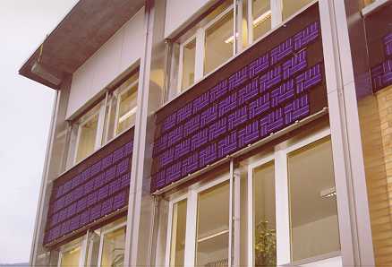
During the next decades, a large part of the world's population will be
introduced to electricity produced by PV systems. These PV systems will make
the traditional requirements of building large, expensive power plants and
distribution systems unnecessary. As the costs of PV continue to decline and as
PV technology continues to improve, several potentially huge markets for PV
will open up. For example, building materials that incorporate PV cells will be
designed right into homes, helping to ventilate and light the buildings.
Consumer products ranging from battery-powered hand tools to automobiles will
take advantage of electricity - producing components containing PV materials.
Meanwhile, electric utilities will find more and more ways to use PV to supply
the needs of their customers.
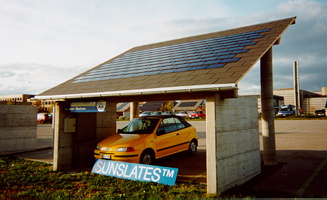
The EU wants to double the share of renewables by 2010, and key actions
include one million PV systems (500,000 roof and the export of 500,000 village
systems) with total installed capacity of 1 GW. BP Amoco (one of the world's
leading marketers of petroleum products) will incorporate solar energy into 200
of its new service stations in Britain, Australia, Germany, Austria,
Switzerland, the Netherlands, Japan, Portugal and Spain, France and the US. The
$50 million program will involve 400 panels, generating 3.5 MW and saving 3,500
tonnes of CO2 emissions every year. The project will make BP Amoco one of
the world's largest users of solar power, as well as one of the largest
manufacturers of cells and modules. The solar panels will generate more power
than consumed for lighting and pump power, and will be grid-connected to allow
excess electricity to be exported during the day and the shortfall imported at
night. The world market for photovoltaics will reach 1,000 MW by 2010 and 5
million MW by 2050, according to the president of BP Solar.
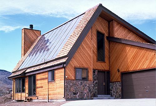
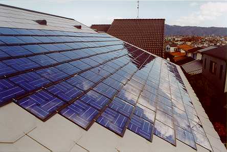
TECHNOLOGY
Solar electric systems are simple to operate and have no moving parts;
however, PV cells employ sophisticated semiconductor devices, many of which are
similar to those developed in the integrated circuit industry. PV cells operate
on the physical principle that electric current will flow between two
semiconductors with different electrical properties when they are put in contact
with each other and exposed to light. A collection of these PV cells
constitutes a PV panel, or module. PV modules, because of their electrical
properties, produce direct rather than alternating current (AC). Direct current
(DC) is electric current that flows in a single direction. Many simple devices,
such as those that run on batteries, use direct current. Alternating current,
in contrast, is electric current that reverses its direction at regular
intervals. This is the type of electricity provided by utilities and required
to run most modern appliances and electronic devices. In the simplest systems,
DC produced by PV modules is used directly. In applications where AC is
necessary, an inverter can be added to the system to convert the DC to AC.
![]()
PV CELLS
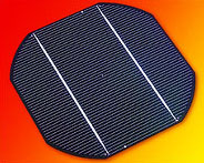 Today's solar cell production
is almost exclusively based on silicon. About 80% of all modules are fabricated
using crystalline silicon cells (multicrystalline and single crystalline) and about
20% are based on amorphous silicon thin film cells. The crystalline cells
are the more common, generally blue-coloured frosty looking ones. Amorphous
means noncrystalline, and these look smooth and change color depending on the
way you hold them. Monocrystalline silicon has the best efficiency -
about 14% of the sunlight can be utilized - but it is more
expensive than multicrystalline silicon, which typically has 11%
efficiency. Amorphous silicon is widely used in small appliances
such as watches and calculators, but its efficiency and long-term
stability are significantly lower; consequently, it is rarely used in
power applications.
Today's solar cell production
is almost exclusively based on silicon. About 80% of all modules are fabricated
using crystalline silicon cells (multicrystalline and single crystalline) and about
20% are based on amorphous silicon thin film cells. The crystalline cells
are the more common, generally blue-coloured frosty looking ones. Amorphous
means noncrystalline, and these look smooth and change color depending on the
way you hold them. Monocrystalline silicon has the best efficiency -
about 14% of the sunlight can be utilized - but it is more
expensive than multicrystalline silicon, which typically has 11%
efficiency. Amorphous silicon is widely used in small appliances
such as watches and calculators, but its efficiency and long-term
stability are significantly lower; consequently, it is rarely used in
power applications.
On a laboratory and/or a pilot production scale there are, however, several
alternative thin film solar cells under development which may penetrate the
market in the future. The most advanced of the presently investigated thin film
systems are:
![]() amorphous
silicon (a-Si: H) cells,
amorphous
silicon (a-Si: H) cells,
![]() cadmium
telluride/cadmium sulfide (CTS) cells,
cadmium
telluride/cadmium sulfide (CTS) cells,
![]() copper
indium diselenide or copper indium/gallium diselenide (CIS or CIGS) cells,
crystalline silicon thin film (c-Si film) cells and
copper
indium diselenide or copper indium/gallium diselenide (CIS or CIGS) cells,
crystalline silicon thin film (c-Si film) cells and
![]() nanocrystalline
dye sensitised electrochemical (nc-dye) cells.
nanocrystalline
dye sensitised electrochemical (nc-dye) cells.
 PV
cells are sandwiches of silicon, the second most abundant material in the
world. Ninety-nine percent of today's solar cells are made of silicon (Si), and
other solar cells are governed by basically the same physics as Si solar cells.
One layer of silicon is treated with a substance to create an excess of
electrons. This becomes the negative or N layer. The other layer is treated
to create a deficiency of electrons, and becomes the positive or P layer.
Assembled together with conductors, the arrangement becomes a light-sensitive
NP junction semiconductor. It's called a semiconductor, because, unlike a wire,
the unit conducts in only one direction; from negative to positive. When
exposed to sunlight (or other intense light source), the voltage is about 0,5
Volts DC, and the potential current flow (amps) is proportional to the light
energy (photons). In any PV, the voltage is nearly constant, and the current is
proportional to the size of the PV and the intensity of the light.
PV
cells are sandwiches of silicon, the second most abundant material in the
world. Ninety-nine percent of today's solar cells are made of silicon (Si), and
other solar cells are governed by basically the same physics as Si solar cells.
One layer of silicon is treated with a substance to create an excess of
electrons. This becomes the negative or N layer. The other layer is treated
to create a deficiency of electrons, and becomes the positive or P layer.
Assembled together with conductors, the arrangement becomes a light-sensitive
NP junction semiconductor. It's called a semiconductor, because, unlike a wire,
the unit conducts in only one direction; from negative to positive. When
exposed to sunlight (or other intense light source), the voltage is about 0,5
Volts DC, and the potential current flow (amps) is proportional to the light
energy (photons). In any PV, the voltage is nearly constant, and the current is
proportional to the size of the PV and the intensity of the light.
Photovoltaic cells are made from hyper pure silicon that is precisely doped
with other materials. The hyper pure silicon substrates used to make PV cells
are very expensive. After all, the same amount of hyper pure silicon used in a
single 50 Watt PV module could have been made into enough integrated circuits
for about two thousand computers. The remainder of the materials used by PV
cells are aluminum, glass, and plastic - all inexpensive and easily recyclable
materials.
PV production
facility.
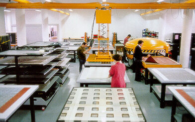
SOLAR
MODULES
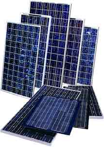 Solar
modules are an array of solar cells which are interconnected and
encapsulated behind a glass cover. The stronger the light falling down on
the cells and the larger the cell surface, the more electricity is
generated and the higher the current. Modules are rated in peak watts
(Wp). A watt is the unit used to express the power of a generator or the
demand of a consumer. One peak watt is a specification which indicates
the amount of power generated under rated conditions, i.e. when solar
irradiance of 1 kW/m2 is incident on the cell at a temperature of 25 deg. C.
This level of intensity is achieved when weather conditions are good and
the sun is at its zenith. No more than a cell of 10 x 10 cm is necessary
to generate a peak watt. Larger modules, 1 m x 40 cm in size, have
an output of about 40-50 Wp. Most of the time, however, the irradiation
is below 1 kW/m2. Furthermore, in sunlight the module will warm up
beyond the rated temperature. Both effects will reduce the module's
performance. For typical conditions an average output of about 6 Wh per
day and 2000 Wh per year per peak watt can be expected. To have the idea
of how much that is, 5 Wh is the energy consumed by a 50 W lamp in 6
minutes (50W x 0,1h = 5Wh) or by a small radio in one hour (5W x 1h =
5Wh).
Solar
modules are an array of solar cells which are interconnected and
encapsulated behind a glass cover. The stronger the light falling down on
the cells and the larger the cell surface, the more electricity is
generated and the higher the current. Modules are rated in peak watts
(Wp). A watt is the unit used to express the power of a generator or the
demand of a consumer. One peak watt is a specification which indicates
the amount of power generated under rated conditions, i.e. when solar
irradiance of 1 kW/m2 is incident on the cell at a temperature of 25 deg. C.
This level of intensity is achieved when weather conditions are good and
the sun is at its zenith. No more than a cell of 10 x 10 cm is necessary
to generate a peak watt. Larger modules, 1 m x 40 cm in size, have
an output of about 40-50 Wp. Most of the time, however, the irradiation
is below 1 kW/m2. Furthermore, in sunlight the module will warm up
beyond the rated temperature. Both effects will reduce the module's
performance. For typical conditions an average output of about 6 Wh per
day and 2000 Wh per year per peak watt can be expected. To have the idea
of how much that is, 5 Wh is the energy consumed by a 50 W lamp in 6
minutes (50W x 0,1h = 5Wh) or by a small radio in one hour (5W x 1h =
5Wh).
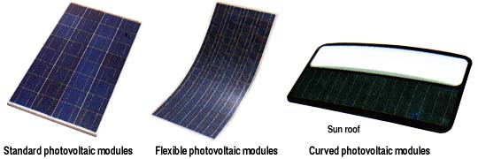
Although some differences still exist in product quality, most international companies produce fairly reliable units which can be expected to work for 20 years. Meanwhile, suppliers guarantee the specified power output for a period of up to 10 years. The most decisive criterion for the comparison of different modules is the price per peak watt. In other words, it is possible to get more power for the money with a 120 Wp module which costs USD 569 (4,74 USD/Wp) than with a cheap 90 Wp module that costs USD 489 (5,43 USD/Wp). The rated efficiency of a system is a less important consideration.
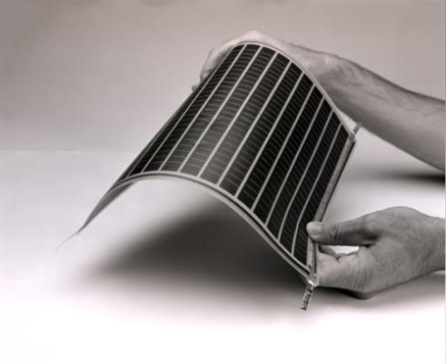
![]()
PV ADVANTAGES
High Reliability
PV cells were originally developed for use in space, where repair is
extremely expensive, if not impossible. PV still powers nearly every
satellite circling the earth because it operates reliably for long periods of
time with virtually no maintenance.
Low Operating Costs
PV cells use the energy from sunlight to produce electricity - the fuel is
free. With no moving parts, the cells require low-maintenance.
Cost-effective PV systems are ideal for supplying power to communication
stations on mountain tops, navigational buoys at sea, or homes far from utility
power lines.
Non-polluting
Because they burn no fuel and have no moving parts, PV systems are clean and
silent. This is especially important where the main alternatives for obtaining power
and light are from diesel generators and kerosene lanterns.
Modular
A PV system can be constructed to any size. Furthermore, the owner of
a PV system can enlarge or move it if his or her energy needs change. For
instance, homeowners can add modules every few years as their energy usage and
financial resources grow. Ranchers can use mobile trailer-mounted pumping
systems to water cattle as they are rotated between fields.
Low Construction Costs
PV systems are usually placed close to where the electricity is used,
meaning much shorter wire runs than if power is brought in from the utility
grid. In addition, using PV eliminates the need for a step-down transformer
from the utility line. Fewer wires mean lower costs and shorter construction
time.
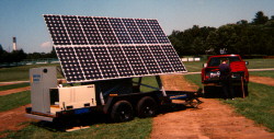
HOW MUCH
DOES PV-GENERATED ELECTRICITY COST?
There is no simple answer. Many small PV systems designed to power a
few fluorescent lights and a small TV in remote hoses are much cheaper than the
next best alternatives running a new power line, replacing and disposing of
primary batteries (those batteries that are used once and then disposed of,
such as flashlight batteries), or using an engine generator. The cost of
electricity from larger systems, those able, for example, to power a modern
home, is evaluated according to the cost per kilowatt hour (kWh). The cost
depends on the initial cost, interest on the loan (for paying the initial
cost), the cost of system maintenance, the expected lifetime of the system, and
how much electricity it produces. Using typical borrowing costs and
equipment life, the cost of PV-generated energy in USA in 1998 ranged
from $0,20 to $0,50/kWh.
HOW MUCH SPACE DOES PV TAKE?
|
|
The most common modules (using cells made from crystalline silicon) generate 100-120 watts per square meter (W/m2). Thus, one square meter module generates enough electricity to power a 100 W light bulb. At the upper end of the range, a PV power plant laid out on a square piece of land measuring approximately 160km on a side could supply all the electricity consumed annually be the entire United States. Better alternative than to use open land area is to place PV modules on the roofs of buildings or integrate them into facades of the walls. This option is usually cheaper because it can replace traditional building materials which have to be used anyway. |
![]()
Simple PV Systems
 The sunlight that creates the
need for water pumping and ventilation can be harnessed using the most basic PV
systems to meet those same needs. Photovoltaic modules produce the most
electricity on clear, sunny days. Simple PV systems use the DC electricity as
soon as it is generated to run water pumps or fans. These basic PV systems have
several advantages for the special jobs they do. The energy is produced where
and when it is needed, so complex wiring, storage, and control systems are unnecessary.
Small systems, under 500 W, weigh less than 70 kilograms making them easy to
transport and install. Most installations take only a few hours. And, although
pumps and fans require regular maintenance, the PV modules require only an
occasional inspection and cleaning.
The sunlight that creates the
need for water pumping and ventilation can be harnessed using the most basic PV
systems to meet those same needs. Photovoltaic modules produce the most
electricity on clear, sunny days. Simple PV systems use the DC electricity as
soon as it is generated to run water pumps or fans. These basic PV systems have
several advantages for the special jobs they do. The energy is produced where
and when it is needed, so complex wiring, storage, and control systems are unnecessary.
Small systems, under 500 W, weigh less than 70 kilograms making them easy to
transport and install. Most installations take only a few hours. And, although
pumps and fans require regular maintenance, the PV modules require only an
occasional inspection and cleaning.
Solar Water Pumping
|
|
Photovoltaic pumping systems provide a welcome alternative to fuel burning generators or hand pumps. They provide the most water precisely when it is needed the most - when the sun shines the brightest! Solar pumps are simple to install and maintain. The smallest systems can be installed by one person in a couple hours, with no experience or special equipment required. |
Advantages of using PV-powered pumps include:
![]() low
maintenance
low
maintenance
![]() ease of
installation
ease of
installation
![]() reliability
reliability
![]() scalability
scalability
Solar power differs fundamentally from conventional electric or
engine-powered systems, so solar pumps often depart from the conventional. PV
arrays produce DC power, rather than the AC from conventional sources. And, the
power available varies with the sun's intensity. Since it costs less to store
water (in tanks) than energy (in batteries) solar pumps tend to be low in
power, pumping slowly through the duration of the solar day.
Simple, efficient systems are the key to economical solar pumping. Special,
low-power DC pumps are used without batteries or AC conversion. Modern DC
motors work well at varying voltage and speed. The better DC motors require
maintenance (brush replacement) only after periods of 5 years or more. Most
solar pumps used for small scale application (homes, small irrigation, livestock)
are positive displacement pumps which seal water in cavities and force it
upward. This differs from faster, conventional centrifugal type pumps (including
jet and submersible pumps) which spin and blow the water up.
Positive displacement pumps include piston, diaphragm, rotary vane, and
pump jacks. They work best for low volumes, particularly where variable running
speeds occur. Centrifugal, jet and turbine pumps are used for higher volume
systems. Electronic matching devices known as Power Trackers and Linear Current
Boosters allow solar pumps to start and run under low-light conditions. This
permits direct use of the sun's power without bothersome storage batteries.
Solar trackers may be used to aim the panels at the sun from morning to sunset,
extending the useable period of sunlight. Storage tanks usually hold a 3-10 day
supply of water, to meet demands during cloudy periods. Solar pumps use
surprisingly little power. They utilize high efficiency design and the long
duration of the solar day, rather than power and speed, to lift the volume of
water required.
In areas where photovoltaic pumps have entered into competition with
diesel-driven pumps, their comparatively high initial cost is offset by the achieved
savings on fuel and reduced maintenance expenditures. Studies concerning the
economic efficiency of photovoltaic pumping systems confirm that they are often
able to yield cost advantages over diesel-driven pumps, depending on the
country-specific situation.
![]()
PV SYSTEMS WITH BATTERIES
The most simple solutions have certain drawbacks - the most obvious
one being that in case of PV powered pump or fan could only be used
during the daytime, when the sun is shining. To compensate for these
limitations, a battery is added to the system. The battery is charged by the
solar generator, stores the energy and makes it available at the times
and in the amounts needed. In the most remote and hostile environments,
PV-generated electrical energy stored in batteries can power a wide variety of
equipment. Storing electrical energy makes PV systems a reliable source of electric
power day and night, rain or shine. PV systems with battery storage are being
used all over the world to power lights, sensors, recording equipment,
switches, appliances, telephones, televisions, and even power tools.
A solar module generates a direct current (DC), generally at a voltage of
12 V. Many appliances, such as lights, TV's, refrigerators, fans,
tools etc., are now available for 12V DC operation. Nevertheless the majority
of common electrical household appliances are designed to operate on 110
V or 220 V alternating current (AC). PV systems with batteries can be designed
to power DC or AC equipment. People who want to run conventional AC equipment
add a power conditioning device called an inverter between the batteries and
the load. Although a small amount of energy is lost in converting DC to AC, an
inverter makes PV-generated electricity behave like utility power to operate
everyday AC appliances, lights, or computers.
PV systems with batteries operate by connecting the PV modules to a battery,
and the battery, in turn, to the load. During daylight hours, the PV modules
charge the battery. The battery supplies power to the load whenever needed. A
simple electrical device called a charge controller keeps the batteries charged
properly and helps prolong their life by protecting them from overcharging or
from being completely drained. Batteries make PV systems useful in more
situations, but also require some maintenance. The batteries used in PV systems
are often similar to car batteries, but are built somewhat differently to allow
more of their stored energy to be used each day. They are said to be deep
cycling. Batteries designed for PV projects pose the same risks and demand the
same caution in handling and storage as automotive batteries. The fluid in
unsealed batteries should be checked periodically, and batteries should be
protected from extremely cold weather.
A solar generating system with batteries supplies electricity when it is
needed. How much electricity can be used after sunset or on cloudy days is
determined by the output of the PV modules and the nature of the battery bank.
Including more modules and batteries increases system cost, so energy usage
must be carefully studied to determine optimum system size. A well-designed system
balances cost and convenience to meet the user's needs, and can be expanded if
those needs change.
![]()
DESIGNING PV HOME SYSTEM WITH BATTERIES
|
|
A solar-powered system with batteries can run quite a lot of consumer devices, but only, of course, if the energy demand does not exceed the generator output. The right sizing of the system is thus necessary. The first step towards having such a system that will provide energy needs is specification of the system. |
CALCULATION OF ENERGY DEMAND
 In case of designing PV powered
home system the first step to make is to create a list of all electrical
appliances in the household. Check the power input required for the operation
of these appliances and put this on the list.
In case of designing PV powered
home system the first step to make is to create a list of all electrical
appliances in the household. Check the power input required for the operation
of these appliances and put this on the list.
As an example average data on power consumption for some devices are in the
table below, but it is important to bear in mind that these are only rough
estimations. To calculate power consumption (E) of the system with inverter
(using AC devices) it is needed to make correction (multiply average
consumption by C to calculate the total power demand Ptot).
|
DEVICE |
Pave |
C |
P tot |
|
Fluorescent lamps |
18 W |
1,5 |
27 W |
|
Radio/Cas.tape,6V |
2W/8W |
2,0 |
4W/16W |
|
Radio/Cas.tape,12V |
8W/12W |
1,0 |
8W/12W |
|
Small b/w TV |
18 W |
1,0 |
18 W |
To operate other electrical appliances such as refrigerators, irons, big fans, cooking plates, etc., you would need a bigger and more expensive system. Since such a system is not standardized but will be tailored specifically to your needs, calculation have to be done by an expert.
Second step is to estimate the amount of time per day that the specific
appliances are in operation. This maybe as much as 10 hours for a lamp in the
living room, but perhaps only 10 minutes for one in the store. Add these data to
your list in a second column in table bellow. Finally, you should make a third
column where you list the daily energy requirement. Calculate this figure by
multiplying the power by the operating period, e.g. 27 W x 4 h = 108 Wh. When
you have added up all the figures in this column, you will have your overall
energy demand (E).
|
DEVICE |
Pave |
No.of h/d |
E |
|
Fluor.Lamp |
27 W |
4 |
108 Wh |
|
Fluor.Lamp |
27 W |
1 |
27 Wh |
|
Fluor.Lamp |
27 W |
0,5 |
13,5 Wh |
|
Radio 6 V |
4 W |
10 |
40 Wh |
|
TV |
15 W |
2 |
30 Wh |
|
Fan |
12 W |
3 |
36 Wh |
|
TOTAL |
|
|
254 Wh |
The next step consists of estimation of the amount of solar insolation which can be expected at home site. In most cases, these figures can be obtained from local PV suppliers or at a local weather station. Important figure is the annual average solar insolation as well as the average in the month with the worst climatic conditions (some general data can be found in chapter on Solar radiation).
Using the first figure, PV system can be adjusted to the average
insolation per year, which means there are some months with more energy than
required or calculated and some months with less. If you use the second (low
case) figure, you will always have at least enough energy to meet your
requirements, except in unusually bad weather periods. However, the PV module
will have to be larger and it will also be more costly.
Now you can calculate the rated power of the PV module. Use your energy
demand figure (in Wh/d), multiply it by 1,7 to allow for energy losses in the
system and divide it by the solar insolation figure (in Wh/d), e.g. 280 (Wh/d)
x 1,7/ 5 (kWh/d) = 96,2 W. Unfortunately, PV modules are only available
with a few power ratings. Using a 50 W module, for example, you can build
generators of 50 W, 100 W, 150 W, etc.. With a power demand of 95 W, a
two-module system would be the best match. Choose the number of modules whose
total power rating corresponds approximately to the value you have calculated.
If the two figures differ significantly, you have to undersize or oversize the
generator. In the first case, the PV system will not be able to meet overall
energy demand. Decide whether this partial supply option would be acceptable to
you. In the second case, you will have surplus energy.
Designing the battery size depends on energy demand and the number of PV
modules. For above mentioned example battery capacity of 60 Ah per module as a
minimum should be used and 100 Ah as an optimum. Such a battery can store 1200
Wh at 12 V. This capacity can cover 4 days of energy needs for above mentioned
example with daily energy consumption of 280 Wh.
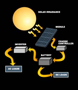
SYSTEM DC
VOLTAGE
In the past, almost all systems used 12 V DC as their base voltage. This was
because the systems were small and extensively employed 12 V DC appliances
powered directly from the battery. Now, with the arrival of efficient and
reliable inverters, 12 Volt use has declined and 24 V DC is becoming the favored
battery voltage. At this moment, the system's DC voltage should be determined
by how much power the system cycles daily. Systems producing and consuming less
than 2,000 Watt-hours daily are best served by 12 Volts. Systems cycling over
2,000 and less than 6,000 Watt-hours daily should use 24 V DC as a base
voltage. Systems cycling over 6,000 Watt-hours daily should use 48 Volts.
System voltage is a very important factor effecting the choice of inverter,
controls, battery chargers, and system wiring. Once these components are
bought, they usually cannot be changed. While some hardware, like PV modules,
can be reconnected from 12 to higher voltages, other hardware like inverters,
controls, and wiring is specified for a particular voltage and must operate
there.
![]()
BATTERY
A battery stores the energy delivered by the solar generator and
provides power for various appliances. As a component of an SHS a battery
has to fulfil three tasks:
![]() It covers
peak loads which the PV modules cannot meet on its own (buffer).
It covers
peak loads which the PV modules cannot meet on its own (buffer).
![]() It
provides energy during the night (short-term storage).
It
provides energy during the night (short-term storage).
![]() It
compensates for periods of bad weather or of unusually high energy
demand (medium-term storage).
It
compensates for periods of bad weather or of unusually high energy
demand (medium-term storage).
 Automotive batteries, which are
available all over the world at reasonable prices, are the most commonly
employed type of battery. However, they are designed to deliver
high currents over short periods. They cannot withstand the continuos
cycles of charging and discharging that are typical for solar systems.
The industry has developed batteries, sometimes called solar batteries,
which meet these conditions. Their main feature is low sensitivity
to cyclic operation.
Automotive batteries, which are
available all over the world at reasonable prices, are the most commonly
employed type of battery. However, they are designed to deliver
high currents over short periods. They cannot withstand the continuos
cycles of charging and discharging that are typical for solar systems.
The industry has developed batteries, sometimes called solar batteries,
which meet these conditions. Their main feature is low sensitivity
to cyclic operation.
Unfortunately, there are only a few developing countries in
which such batteries are produced, and imported batteries may be very
expensive owing to transport costs and customs duties. In such cases, a
heavy-duty truck battery may be an appropriate, easily accessible
alternative, even if it has to be replaced more often.
In the case of large PV systems, the capacity of one battery may not
be sufficient. If so, more than one battery, can be switched in
parallel, i.e. all poles marked + and all marked - are connected to each
other. Thick copper wires, preferably less than 30 cm long, should
be used for the connection. During charging, batteries produce gases
which are potentially explosive. Thus, you should avoid using an open fire
nearby. However, gassing is relatively low, especially if a charge
regulator is used; the risk is thus no greater than that normally
involved in the use of automotive batteries in cars. Nevertheless,
the batteries need to be well ventilated. Therefore you should not cover
them up or put them in boxes.
The capacity of a battery is indicated in ampere-hours (Ah). A 100
Ah, 12 V battery, for instance, can store 1,200 Wh (12 V x 100 Ah).
However, the capacity will vary, depending on the duration of the
charging or discharging process. In other words, a battery will
deliver more energy during a 100 h discharging period than during a 10 h
period. The charging period is indicated by an index to the
capacity c, e.g. C100 for 100 hours. Note that suppliers may use different
reference periods.
When storing energy in batteries, a certain amount of energy is lost
in the process. Automotive batteries have efficiencies of about
75%, while solar batteries may perform slightly better. Some of the
battery capacity is lost in each charging-discharging cycle and eventually
drops to a level at which the battery has to be replaced. Solar
batteries have a longer lifetime than heavy-duty automotive batteries,
which last about 2 or 3 years.
SIZING THE PV SYSTEM'S
BATTERY
It is important to size the PV systems battery with a minimum of four days
of storage. Consider the system that consumes 2,480 watt-hours daily. If we
divide this figure by system voltage of 12 V DC, we arrive at a daily
consumption of 206 Ampere-hours from the battery. So four days of storage would
be 4 days X 206 Ampere-hours per day or 826 Ampere-hours. If the battery is a
lead-acid type, then we should add 20% to this amount to ensure that the
battery is never fully discharged. This brings our ideal lead-acid battery up
to a capacity of 991 Ampere-hours. If the battery is nickel-cadmium or
nickel-iron, then this extra 20% capacity is not required because alkaline
batteries don't mind being fully discharged on a regular basis.
![]()
THE CHARGE REGULATOR
 A
battery can only be expected to last several years if a good charge
regulator is employed. It protects the battery against overcharging and
deep-discharging, both of which are harmful to the battery. If a battery
is fully charged, the regulator reduces the current delivered by the
solar generator to a level which equalizes the natural losses. On the other
hand, the regulator interrupts the amount of energy supplied to the
load appliances when the battery has discharged to a critical level.
Thus, in most cases a sudden interruption in supply is not a system
failure, but rather an effect of this safeguard mechanism.
A
battery can only be expected to last several years if a good charge
regulator is employed. It protects the battery against overcharging and
deep-discharging, both of which are harmful to the battery. If a battery
is fully charged, the regulator reduces the current delivered by the
solar generator to a level which equalizes the natural losses. On the other
hand, the regulator interrupts the amount of energy supplied to the
load appliances when the battery has discharged to a critical level.
Thus, in most cases a sudden interruption in supply is not a system
failure, but rather an effect of this safeguard mechanism.
Charge regulators are electronic components and, as such, may be affected by
malfunctions and improper handling of the systems. Improved designs
are equipped with safeguards to prevent damages to the regulator and
other components. These include safeguards against short circuit and
battery reverse polarity (mixing up of the batteries' +/- poles) as well
as a blocking diode to prevent overnight battery discharge. Many models
indicate certain states of operation and malfunctions by means of LEDs
(light emitting diodes = small lamps). A few even indicate the state of
charge. Nevertheless the state of charge is difficult to determine and
can only be roughly estimated.
THE INVERTER
 The
inverter converts low voltage DC power (stored in the battery and produced by
the PVs) into standard alternating current, house power (120 or 240 V AC, 50 or
60 Hz). Inverters come in sizes from 250 watts (about 300 USD) to over 8,000
watts (about 6,000 USD). The electric power produced by modern sine wave
inverters is far purer than the power delivered to your wall sockets by your
local electric utility. There are also modified sine wave inverters that are
less expensive yet still up to most household tasks. This type of inverter may
create a buzz in some electronic equipment and telephones which can be a minor
problem. The better sine wave inverters have made great improvements in
performance and price in recent years. Inverters can also provide a utility
buffer between your system and the utility grid, allowing you to sell your
excess power generated back to the utility for distribution by their grid.
The
inverter converts low voltage DC power (stored in the battery and produced by
the PVs) into standard alternating current, house power (120 or 240 V AC, 50 or
60 Hz). Inverters come in sizes from 250 watts (about 300 USD) to over 8,000
watts (about 6,000 USD). The electric power produced by modern sine wave
inverters is far purer than the power delivered to your wall sockets by your
local electric utility. There are also modified sine wave inverters that are
less expensive yet still up to most household tasks. This type of inverter may
create a buzz in some electronic equipment and telephones which can be a minor
problem. The better sine wave inverters have made great improvements in
performance and price in recent years. Inverters can also provide a utility
buffer between your system and the utility grid, allowing you to sell your
excess power generated back to the utility for distribution by their grid.
CABLES
A simple means of avoiding unnecessary losses is to use appropriate
cables and to attach them properly to the devices. Cables should always
be as short as possible. The ones connecting the different appliances
should have a cross-sectional area of at least 1.6 mm2. To ensure
that the voltage loss does not exceed 3%, the cable between the PV generator
and the battery should have a cross-section of 0.35 mm2 (12 V- system) or
0.17 mm2 (24 V-system) per metre and module. Thus, a 10 m cable for 2
modules would require at least 10 x 2 x0,35 mm2 = 7 mm2. Since cables
with a cross-section exceeding 10 mm2 are difficult to handle and even
difficult to get, higher losses have to be accepted in some cases. If a
part of this cable is exposed to the open air, it should be designed so that
will withstand all weather conditions. Tolerance to ultraviolet rays may be an
important feature.
TRACKERS
PV modules work best when their cells are perpendicular to the Sun's
incoming rays. Adjustment of static mounted PV modules can result in from 10%
(in winter) to 40% (in summer) more power output yearly. Tracking means mounting
the array on a movable platform which follows the sun's daily motion. A tracker
is a special PV mounting rack that follows the path of the sun. In general the
extra energy captured by following the sun must be weighed against the costs of
installing and maintaining the tracking system.
Trackers cost money just like PV modules. In many countries it is not cost
effective to track less than eight modules (e.g. in the USA). Under eight
modules, we will get more power output for money if we spend the money on more
panels rather than a tracker. At eight panels in the system, the tracker starts
to pay off. There are exceptions to this rule, for example array direct water
pumps. If PVs are directly driving a water pump, without a battery in the
system, then it is cost effective to track two or more PV modules. This has to
do with technical details like the peak voltage required to drive the pumps
electric motor.
THE LAMPS
Due to their excellent efficiency and long lifetime, energy saving
lamps should always be used in PV operated systems. Fluorescent tubes or the
new compact fluorescent lamps (CFL) are suitable in many cases, 18 W CFL lamp
is able to substitute traditional 100 W incadescent light bulb. CFL lamps
require electronic ballasts to be operated with a DC system. The quality of
such ballasts varies considerably and sometimes proves to be very poor.
Low-quality ballasts will result in high costs for continuous replacement of
worn-out tubes. It is important for ballasts to have a good efficiency, a high
number starting cycles, reliable ignition at low temperatures and low voltages
(10.5 V), and protection against short-circuit, open circuit, reverse polarity
and radio interference. Despite the fact that most CFL lamps on the market are
working only with AC current there are few companies offering also DC powered
lamps.
![]()
LIFETIME AND PRICING OF
COMPONENTS
A very important consideration in the economic analysis is the lifetime of a
PV system. Lifetimes of the various components of a PV power supply have been
estimated, based on experiences gained over the past few years.
![]() The
lifetime of PV panels is estimated at 20 years. Proper encapsulation and the
use of low-iron tempered glass ensure a lifetime which may go well beyond.
The
lifetime of PV panels is estimated at 20 years. Proper encapsulation and the
use of low-iron tempered glass ensure a lifetime which may go well beyond.
![]() Galvanized
iron frames and anchors are part of most PV systems. Properly galvanized
material should last as long as the panels although some
Galvanized
iron frames and anchors are part of most PV systems. Properly galvanized
material should last as long as the panels although some
maintenance may be required.
![]() Batteries.
Depending on the character of the charge/discharge cycles, the average lifetime
of the so-called Solar Batteries, has been 4 years.
Batteries.
Depending on the character of the charge/discharge cycles, the average lifetime
of the so-called Solar Batteries, has been 4 years.
![]() Battery
chargers are assumed to last at least 10 years.
Battery
chargers are assumed to last at least 10 years.
![]() Inverters
are assumed to last for 10 years.
Inverters
are assumed to last for 10 years.
Rough guidelines for pricing of the several components:
![]() Inverters -
USD 0.50/W
Inverters -
USD 0.50/W
![]() Frames
(galvanized) - USD 0.30/Wp
Frames
(galvanized) - USD 0.30/Wp
![]() Control
Devices - USD 0.50/Wp
Control
Devices - USD 0.50/Wp
![]() Cables -
USD 0.70/m
Cables -
USD 0.70/m
![]() Local
stationary batteries - USD 100/kWh capacity
Local
stationary batteries - USD 100/kWh capacity
![]() PV modules
- USD 5 /Wp.
PV modules
- USD 5 /Wp.
PV WITH GENERATORS
Working together, PV and other electric generators can meet more varied
demands for electricity, conveniently and for a lower cost than either can meet
alone. When power must always be available or when larger amounts of
electricity than a PV system alone can supply are occasionally needed, an
electric generator can work effectively with a PV system to supply the load.
During the daytime, the PV modules quietly supply daytime energy needs and charge
batteries. If the batteries run low, the engine-generator runs at full power
its most constant fuel-efficient mode of operation until they are charged. And
in some systems the generator makes up the difference when electrical demand
exceeds the combined output of the PV modules and the batteries. Systems using
several types of electrical generation combine the advantages of each.
Engine-generators can produce electricity any time. Thus, they provide an
excellent backup for the PV modules (which produce power only during daylight
hours) when power is needed at night or on cloudy days. On the other hand, PV
operates quietly and inexpensively, and does not pollute. Using PV and
generators together can also reduce the initial cost of the system. If no other
form of generation is available, the PV array and the battery storage must be
large enough to supply night time electrical needs.
However, having an engine-generator as backup means fewer PV modules and
batteries are necessary to supply power whenever it is needed. Including
generators makes designing PV systems more complex, but they are still easy to
operate. In fact, modern electronic controllers allow such systems to operate
automatically. Controllers can be set to automatically switch generators or to
supply AC or DC loads or some of each. In addition to engine generators,
electricity from wind generators, small hydro plants, and any other source of
electrical energy can be added to make a larger hybrid power system.
![]()
GRID-CONNECTED PV
|
|
Where utility power is available, a grid-connected home PV system can supply some of the energy needed and use the utility in place of batteries. Several thousands of homeowners around the world are using PV systems connected to the utility grid. They are doing so because they like that the system reduces the amount of electricity they purchase from the utility each month. They also like the fact that PV consumes no fuel and generates no pollution. The owner of a grid-connected PV system buys and sells electricity each month. Electricity generated by the PV system is either used on site or fed through a meter into the utility grid. When a home or business requires more electricity than the PV array is generating, for example, in the evening, the need is automatically met by power from the utility grid. When the home or business requires less electricity than the PV array is generating, the excess is fed (or sold ) back to the utility. Used this way, the utility backs up the PV like batteries do in stand-alone systems. At the end of the month a credit for electricity sold gets deducted from charges for electricity purchased. In some countries utilities are required to buy power from owners of PV systems (and other independent producers of electricity). |
An approved, utility-grade inverter converts the DC power
from PV modules into AC power that exactly matches the voltage and frequency of
the electricity flowing in the utility line, and also meets the utility safety
and power quality requirements. Safety switches in the inverter automatically
disconnect the PV system from the line if utility power fails. This safety
disconnect protects utility repair personnel from being shocked by electricity
flowing from the PV array into what they would expect to be a dead utility
line. In some countries utilities are establishing rate structures that may
make PV grid-connected systems more economical. (At todays prices, when the
cost of installing a utility-connected PV system is divided by the amount of
electricity it will produce over 30 years, PV- generated electricity is almost
everywhere more expensive than power supplied by the utility.) For example,
some utilities charge higher prices at certain times of the day. In some parts
of the USA, the highest charges for electricity under this time-of-day pricing
structure are now nearly equal to the cost of energy from PV. The better the
match between the electrical output of the PV modules and the time of highest
prices, the more effective the system will be in reducing utility bills.
Grid connected systems are growing especially in USA and Europe. One such a
project was commissioned in California. Twelve homes in a major housing
development in Compton (southern California) are using integrated solar roof
tiles to provide household electricity from sunlight. Central Park
Estates, an affordable single-family housing development, uses solar roof tiles
as an integral and aesthetically pleasing part of the homes. The solar roofs are
connected to the local power grid, and meters will spin backwards' when the PV
cells produce excess power.
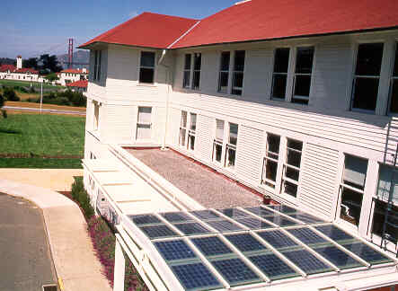
UTILITY-SCALE PV
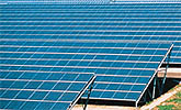 Electric,
gas, and water utilities have been using small PV systems economically for
several years. Most of these systems are less than 1 kW and use batteries for
energy storage. These systems are performing many jobs for utilities, from
powering aircraft warning beacons on transmission towers to monitoring air
quality of fluid flows. They have demonstrated the reliability and durability
of PV for utility applications and are paving the way for larger systems to be
added in the future.
Electric,
gas, and water utilities have been using small PV systems economically for
several years. Most of these systems are less than 1 kW and use batteries for
energy storage. These systems are performing many jobs for utilities, from
powering aircraft warning beacons on transmission towers to monitoring air
quality of fluid flows. They have demonstrated the reliability and durability
of PV for utility applications and are paving the way for larger systems to be
added in the future.
Utilities are exploring PV to expand generation capacity and meet increasing
environmental and safety concerns. Large-scale photovoltaic power plants,
consisting of many PV arrays installed together, can prove useful to utilities.
Utilities can build PV plants much more quickly than they can build
conventional power plants because the arrays themselves are easy to install and
connect together electrically. Utilities can locate PV plants where they are
most needed in the grid because siting PV arrays is much easier than siting a
conventional power plant. And unlike conventional power plants, PV plants can
be expanded incrementally as demand increases. Finally, PV power plants consume
no fuel and produce no air or water pollution while they silently generate
electricity. Unfortunately, PV generation plants have several characteristics
that have slowed their use by utilities. Under current utility accounting,
PV-generated electricity still costs considerably more than electricity
generated by conventional plants. Furthermore, photovoltaic systems produce
power only during daylight hours and their output varies with the weather.
Utility planners must therefore treat a PV power plant differently than a
conventional plant in order to integrate PV generation into the rest of their
power generation, transmission, and distribution systems. On the other hand,
utilities are becoming more involved with PV. For example in USA utilities are
exploring connecting PV systems to the utility grid in locations where they
have a higher value. For example, adding PV generation near where the
electricity is used avoids the energy losses resulting from sending current
long distances through the power lines. Thus, the PV system is worth more to
the utility when it is located near the customer. PV systems could also be installed
at locations in the utility distribution system that are servicing areas whose
populations are growing rapidly. Placed in these locations, the PV systems
could eliminate the need for the utility to increase the size of the power
lines and servicing area. Installing PV systems near other utility distribution
equipment such as substations can also relieve overloading of the equipment in
the substation.
Photovoltaics are unlike any other energy source that has ever been
available to utilities. PV generation requires a large initial expense, but the
fuel costs are zero. Coal- or gas- fired plants cost less to build initially
(relative to their output) but require continued fuel expense. Fuel expenses
fluctuate and are difficult to predict due to the uncertainty of future
environmental regulations. Fossil fuel prices will rise over time, while the
overall cost of PVs (and all renewable energy resources) is expected to
continue to drop, especially as their environmental advantages are valued.
PV ELECTRICITY COST
The table below shows calculated electricity cost produced by PV system
in US cents per kWh as function of the investment cost and the efficiency. The
row headings on the left show the total cost, per peak kW (kWp), of a
photovoltaic installation. The column headings across the top refer to the
annual energy output in kilowatt-hours expected from each installed peak
kilowatt. This varies by geographic region (see the figure for Europe). It also
depends on the path of the sun relative to the panel and the horizon.
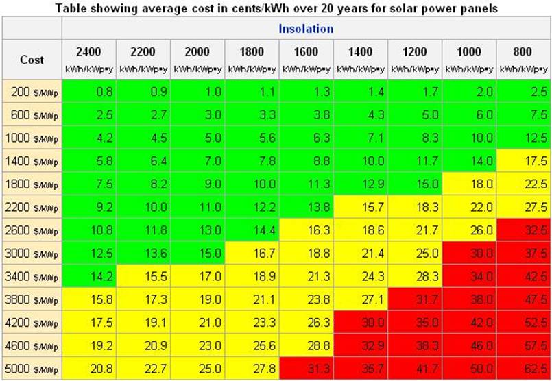
Source: Wikipedia
Insolation in Europe can be seen from the figure bellow.
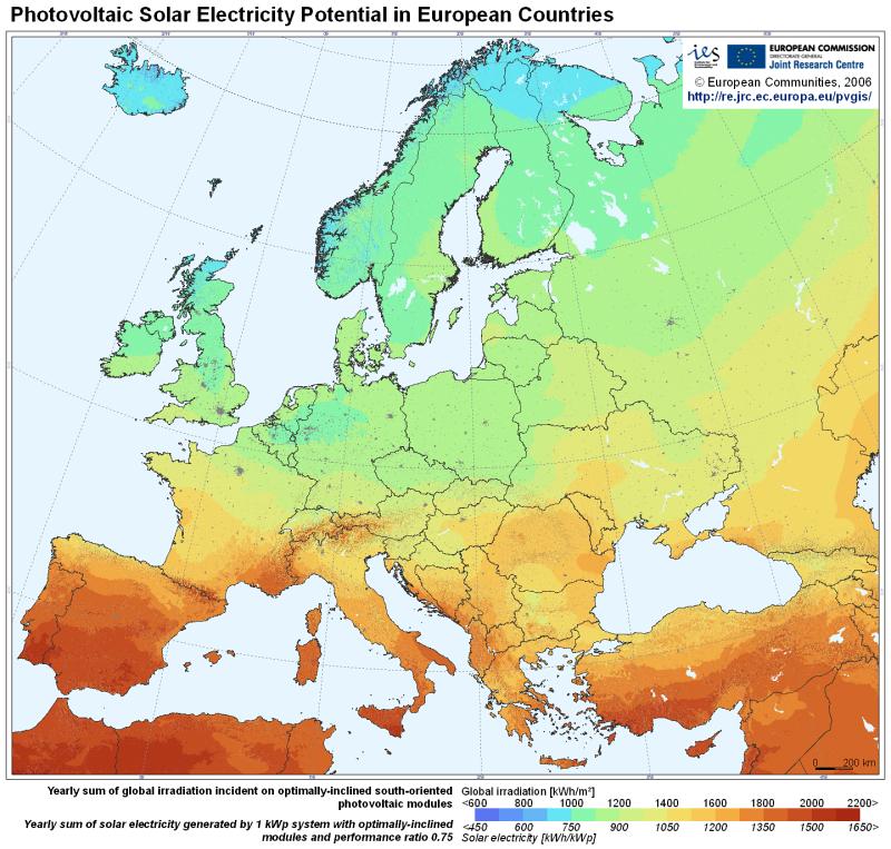
Key to
the PV development in the future are the costs of
investment. And they tend to be falling steadily due to the decreasing costs of
PV modules. Especially PV modules made from thin-films already reached the
production price level bellow 1000 USD/kWp (2009) which is making them
attractive option in several regions of the world even without governmental
subsidies. Several experts predict that many PV producing companies will reach the
cost of 1 USD/W before 2012. This target will be a huge competition factor for
consumers and businesses because then PV panels will be able to generate power
cheaper than other fossil fuel sources in numerous regions of the world. With price
of PV modules less than 1 USD per Watt, solar electricity could be produce for less
than 0,1 USD/kWh (see the figure above) and that is
highly competitive. The average price of electricity in Europe and U.S is
higher than this and due to the fossil fuel scarcity is expecting to rise in
the future.
![]()
Guideline for Estimation of Solar Potentials, Barriers and Effects
Solar
heating
This section is mainly covering active solar heating, where the solar energy
is transferred to heat in solar collectors and from there transported by a
fluid to its final use. Another important use of solar heat is passive solar
heating, where buildings are designed to capture the maximum of the solar
energy coming through windows and upon walls to be used for space-heating.
Energy Content
The yearly incoming solar energy varies from 900-1000 kWh/m2 North of the
Baltic Sea to e.g. 1077 kWh/m2 in Central Europe (Hradec Kralove in Bohemia)
and up to 1600 kWh/m2 in Mediterranean and Black Sea areas on a horizontal
surface. On a south sloping surface, the incoming solar energy is about 20%
higher.
Resource Estimation
The incoming solar energy on most buildings exceed the energy consumption of
the building, e.g. a 5 storey apartment house in Hradec Kralove receives 1077
kWh/m2, while each storey consumes about 150 kWh/m2 for heating and 25-50
kWh/m2 for light and cooking, adding up to 875 - 1000 kWh/m2 for the 5 storeys
together (all measured per. m2 horizontal surface).
While the incoming solar energy is sufficient over the year, the practical
usable resource is limited by the fluctuations of the solar energy and the
storage capacity. Reasonable good estimates of usable solar heat can be made as
a fraction of the different heat demands.
For house-integrated systems, the limitations are normally that solar heating can only cover 60-80% of the hot water demand and 25 - 50% of space heating. The variations are depending on location and systems used. In Northern Europe the limitations are respectively 70% and 30% for hot water and space heating coverage.
For central solar heating systems for district heating, analyses and experience show that these systems can cover 5% of consumption without storage, 10% with 12 hour storage and about 80% with seasonal storage. These figures are based on district heating systems which have 20% average energy losses and mainly deliver to dwellings. The energy delivered from solar heating systems without storage is by far the cheapest solution.
For industries that uses heat below 100oC, solar heating can cover about
30% if they have a steady consumption of heat. For drying processes solar
energy can cover up to 100% depending on season, temperature, and limitations
to drying period.
Solar heating to swimming pools can cover most of the heat demand for indoor
pools and up to 100% for outdoor pools used during summer.
To evaluate the potential for solar heating is, thus, most a question of assessing the demand for low-temperature heat.
Barriers
Most applications for solar heating are well developed, and the technical
barrier is more lack of local availability of a certain technology than lack of
the technology as such. Thus the main barriers, beside economy, are:
![]() lack of
information of available technologies and their optimal design and integration
in heating systems.
lack of
information of available technologies and their optimal design and integration
in heating systems.
![]() lack of
local skills for production and installation.
lack of
local skills for production and installation.
In some occasions lack of access to solar energy can be a barrier. For
active solar heating it is almost always possible to find a place for the solar
collectors with enough sunshine. For passive solar energy, where the solar
energy is typically coming through normal windows, neighbouring buildings or
high trees can give a severe reduction of the solar energy gain.
![]()
Effect on economy, environment
and employment
Economy
The economy of using solar energy ranges from almost no costs, when simple
passive solar energy designs are integrated into building design and land-use
planning to very high costs for solar heating systems with seasonal storage.
For solar heating systems, some typical prices are for installed systems:
|
Application |
Collector size |
Annual production |
Invest./area |
Invest./annual production |
|
Single family hot water, Northern |
4-6 m2 |
2,000 kWh |
1000 EUR/m2 |
2.5 EUR/kWh |
|
Single family hot water, South EU |
4 m2 |
2,500 kWh |
250 EUR/m2 |
0.4 EUR/kWh |
|
Swimming pool, outdoor |
100 m2 |
10,000 kWh |
10 EUR/m2 |
0.1 EUR/kWh |
|
District heating |
1000 m2 |
440 kWh/m2 |
181 EUR/m2 |
0.41 EUR/kWh |
Notes:
The application for single family hot water, Northern is a typical system for
hot water as used in Nordic countries and Germany with anti-freeze agent, high
insolation, and closed circuit. The single family Southern Europe is a single
family system as used in Greece. Prices in Central & Eastern Europe can be
considerably lower. Self-built systems are also considerably cheaper.
The annual production is given for Northern European conditions, except for
the Southern European single family system, where production is given for
Southern European conditions.
The savings are net savings, in most applications in Northern Europe, the
solar heat replaces an oil or gas boiler that has a very low efficiency (often
30-50%) during summer. The total savings can then be 2-3 times larger than the
net savings.
Environment
The heat produced in a solar heater replaces energy produced in more
polluting ways, which is the main environmental effect. The energy produced to
produce a solar heater is equivalent to 1-4 years of production of the solar
heater.
Usually the solar collectors are mounted on top of a roof, in which case
there is no local impact of the environment.
Effects of employment
The majority of the employment is in the production and installation of
solar heaters. Based on Danish experience, the employment is estimated to 17
man-years to produce and install 1,000 m2 of solar heaters for families. These
1,000 m2 replaces 800 MWh of primary energy (net energy production 400 MWh).
With 30 years lifetime of the solar heaters, the constant employment of
producing solar heaters to replace 1 TWh will be 700 persons.
Country Estimates
In principle all heat demand can be covered by solar energy with seasonal
storage. There is therefore no absolute limit to this resource, only economical
limitations. In Denmark it is estimated that without seasonal storage, solar
energy can cover 13% of the heat demand, including commercial and industrial
use. In more sunny places, this fraction is naturally larger.
Photovoltaics Electricity
Photovoltaic (PV) cells produce direct current electricity with output varying
directly with the level of solar radiation. PV cells are integrated in modules
which are the basic elements of PV systems. PV modules can be designed to
operate at almost any voltage, up to several hundred Volt, by connecting cells
and modules in series. For applications requiring alternating current,
inverters must be used.
![]()
PV cell efficiency is calculated as the percentage difference between the
irradiated power (Watt) per area unit (m2), and the power supplied as electric
energy from the photovoltaic cell. There is a distinction between theoretical
efficiency, laboratory efficiency, and practical efficiency. It is important to
know the difference between these terms, and it is of course only the practical
efficiency which is of interest to users of photovoltaics.
Practical efficiency of mass produced PV cells:
single crystalline silicon : 16 - 17%
polycrystalline silicon : 14 - 15%
amorphous silicon : 8 - 9%
PV systems are usually divided in:
1. Stand-alone systems that rely on PV power
only. Beside the PV modules they include charge controllers and batteries.
2. Hybrid systems that consists of a combination
of PV cells and a complementary means of electricity generation such as wind,
diesel or gas. Often smaller batteries and chargers/controllers are also used
in these systems.
3. Grid connected systems, which work as small
power stations feeding power into the grid.
Tips and Applications
When designing a photovoltaic installation a number of things must be taken
into consideration, if an optimum solution is wanted. At first it must be
clarified, how much energy is demanded from the photovoltaic installation.
After that the total daily consumption in Ampere hours (Ah) must be estimated.
From the total daily and weekly consumption the total energy storage capacity
can be calculated. It must be considered how many days without sun, the
installation shall be capable of functioning. At the end it can be calculated,
how many photovoltaic modules are required to produce sufficient energy. The
photovoltaic application can also be combined with other energy sources. A
combination of small wind generators and photovoltaics is an obvious
possibility. The energy can be stored in good lead batteries (solar batteries,
traction-batteries) or in nickel/cadmium batteries.
Resource estimation
The solar energy which is available during the day varies because of the
relative motion of the sun, and depends strongly on the local sky conditions.
At noon in clear sky conditions, the solar irradiation can reach 1000 W/m2
while, in very cloudy weather, it may fall to less than 100 W/m2 even at midday.
The availability of solar energy varies both with tilt angle and the
orientation of surface, decreasing as the surface is moved away from South.
Commercial cells are sold with rated output power (Watt peak power, Wp). This corresponds to their maximum output in standard test conditions, when the solar irradiation is near to its maximum at 1000 W/m2, and the cell temperature is 25oC. In practice, PV modules seldom work at these conditions. Rough estimate of the output (P) from PV systems can be made according to the equation:
P (kWh/day) = Pp (kW) * I (kWh/m2 per day) * PR
where:
Pp is rated output power in kW, which is equivalent to efficiency *
area in m2
I is solar irradiation on the surface, in kWh/m2 per day
PR is Performance Ratio determined by the system.
![]()
Daily mean solar irradiation
(I) in Europe in kWh/m2 per day (sloping south, tilt angle from horizon 30
deg.):
|
|
South Europe |
Central Europe |
North Europe |
|
January |
2,6 |
1,7 |
0,8 |
|
February |
3,9 |
3,2 |
1,5 |
|
March |
4,6 |
3,6 |
2,6 |
|
April |
5,9 |
4,7 |
3,4 |
|
May |
6,3 |
5,3 |
4,2 |
|
June |
6,9 |
5,9 |
5,0 |
|
July |
7,5 |
6,0 |
4,4 |
|
August |
6,6 |
5,3 |
4,0 |
|
September |
5,5 |
4,4 |
3,3 |
|
October |
4,5 |
3,3 |
2,1 |
|
November |
3,0 |
2,1 |
1,2 |
|
December |
2,7 |
1,7 |
0,8 |
|
YEAR |
5,0 |
3,9 |
2,8 |
Typical Performance Ratios:
0.8 for grid connected systems
0.5 - 0.7 for hybrid systems
0.2 - 0.3 for stand alone systems for all year
use
|
For more World Solar Irradiation Data go to : CD directory named SOFT and double click on sunny.exe |
![]()
Typical System Performance
Stand alone systems have low yields because they operate with an almost constant
load throughout the year and their PV modules must be sized to provide enough
energy in winter even though they will be oversized during summer.
Typical professional systems in Europe have annual average yields of 200 -
550 kWp.
Hybrid systems have higher performance ratio, because they can be sized
to meet the required load in the summer and can be backed up by other systems
like wind or diesel in the winter and in bad weather.
Typical annual average yield is 500 - 1250 kWh/kWp depending on the losses
caused by the charge controller and the battery.
Grid connected systems have the highest Performance Ratio because all of
the energy which they produce can either be used locally or exported to the
grid.
Typical annual yield is 800 - 1400 kWh/kWp.
Barriers
Despite a sharp decline in costs, PV cells currently cost 5 US$/Wp (4
ECU/Wp). Electricity generation costs is currently 0.5 - 1 ECU/kWh, which is
higher than from other renewable energy sources. In the future, the costs of PV
are expected to fall with increasing utilization. Despite its high costs, PV
electricity can be cheaper than other sources in remote areas without electric
grid and where production of electricity by other means like diesel is
difficult or environmentally unacceptable (mountain areas).
Effects on economy,
environment and employment
When the only cost-effective applications of PV systems in Europe are remote
areas without electric grid, it will have a positive economical effect only for
those areas.
There are no environmental effects of using PV systems. Environmental problems can occur in the production of the cells, and in the production and (improper) disposal of the batteries.
The use of PV is not expected to have any measurable employment effect in
Europe for the time being.
![]()
Hand Rule
In a typical photovoltaic system based on crystalline Silicon with 12%
efficiency each kWp of installed power capacity can produce 1150 kWh of
electricity per year for grid connected systems and 300 kWh/year for stand
alone systems in Central Europe.
TOP
![]()