|
|
|
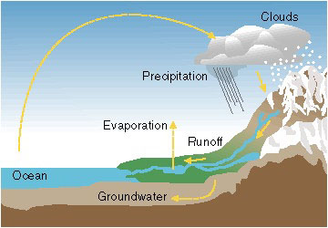 Water constantly
moves through a vast global cycle, in which it evaporates (due to the activity
of the Sun) from oceans, seas and other water reservoirs, forms clouds,
precipitates as rain or snow, then flows back to the ocean. The energy
of this water cycle, which is driven by the sun, is tapped most efficiently
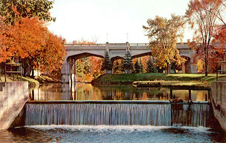
with hydropower. The use of water to generate mechanical power is a very
old practice. A flowing stream can make a paddle turn, but a waterfall
can spin a blade fast enough to generate electricity. The real key in the
magnitude of waterpower is the physical height difference achieved between
source and sink - the distance through which the water falls.
Water constantly
moves through a vast global cycle, in which it evaporates (due to the activity
of the Sun) from oceans, seas and other water reservoirs, forms clouds,
precipitates as rain or snow, then flows back to the ocean. The energy
of this water cycle, which is driven by the sun, is tapped most efficiently
with hydropower. The use of water to generate mechanical power is a very
old practice. A flowing stream can make a paddle turn, but a waterfall
can spin a blade fast enough to generate electricity. The real key in the
magnitude of waterpower is the physical height difference achieved between
source and sink - the distance through which the water falls.
Another methods of harnessing water's energy include utilisation
of the temperature of ocean water in a thermal transfer process, waves
and tidal power. The waves are a direct result of wind, which itself is
cause by uneven heating of the ground and oceans by the Sun. Of the several
types of hydropower, only the origin of the tides is not related to the
Sun. The gravitational pull of the moon is responsible for the tides, which
vary in magnitude by location according to latitude and geography.
When considered as a whole, the energy locked within Earth's water cycle and ocean waves is extremely large, but harnessing this energy has proved to be exceedingly difficult. There are many different ways to harness the energy in water. The most common way of capturing this energy is hydroelectric power, electricity created by falling water.
The principal advantages of using hydropower are its large renewable domestic resource base, the absence of polluting emissions during operation, its capability in some cases to respond quickly to utility load demands, and its very low operating costs. Hydroelectric projects also include beneficial effects such as recreation in reservoirs or in tail water below dams. Disadvantages can include high initial capital cost and potential site-specific and cumulative environmental impacts.
HISTORY
Simple water-wheels have been used already in ancient times to
relieve man of some forms of hard manual labour. Water power was probably
first mentioned by the Greeks, around 4000 B.C. Greeks used hydro power
to turn water wheels for grinding wheat into flour as well. Much later,
but long before the advent of the steam engine, the art of building
large water-wheels and the use of considerable power capacities was highly
developed. The use of this natural energy resource became even easier
and more widespread with the invention of the water turbine in the
early 1800's and hydro power was quickly adapted from mechanical uses,
such as grist mill, to spinning a generator to produce electricity. The
first small industries emerged soon after in many regions of Europe and
North America, powered by water turbines.
In later years, when cheap oil became available world-wide, interest
in hydro power was lost to a great extent in many areas, but today
the situation is different again. Governments, policy-makers, funding
and lending agencies, institutions and individuals take a growing
interest. This led -and still does -to the reassessment of many projects
once found not feasible; the identification of new sites and potentials,
and a number of other activities related to hydro development.
![]()
HYDRO
POWER PLANTS
Amongst renewable energy sources, hydroelectric power seems to be
the most desirable for utilities and its economic feasibility has been
successfully proven. Power stations with a capacity of up to 10 GW have
been built and it is estimated that there are economic resources for 3,000
GW world-wide, compared to 10,000 GW world primary energy consumption.
In Europe, however, most hydroelectric potential has been realised, with
Norway deriving 98% of its energy consumption from water power and the
West German government concluding that there are no more sites available
for exploitation. World-wide it is estimated that about 10% of resources
have been realised, with most potential remaining in Africa and Asia.
Consumption of hydro power in the world.
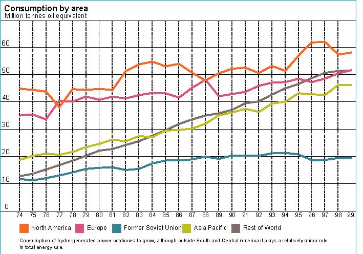
Present worlds total installed hydro power capacity is about 630 000 MW. The data are uncertain because the contributions from small hydro power plants and private systems are difficult to estimate, but it is assumed that these facilities can add just a few per cent to the total figure. The annual power production world-wide is 2200 TWh (billion kilowatt hours), which means that the power plants are running at 40 % of its rated power.
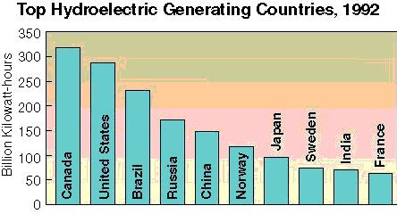
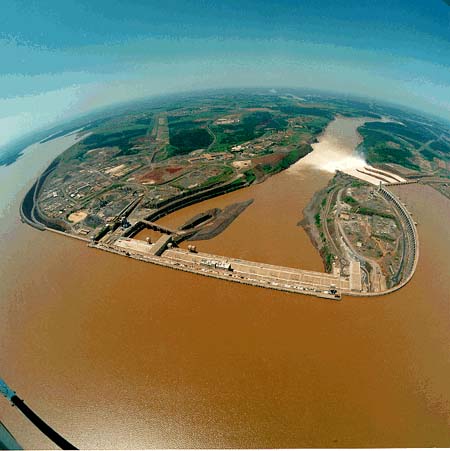
The largest hydroelectric complex in the world is on the Parana River, between Paraguay and Brazil. It is called the Itaipu Dam and its 18 turbines produce 12 600 MW of electricity. Hydro power is growing in many regions of the world. China and India pledged increases in large-scale hydroelectric development. In 1999 China completed its 3300 MW Ertan hydroelectric station which has six generating units, each with a capacity of 550 megawatts. Ertan is Asia's second tallest dam and China's largest electricity supplier.
The largest hydro power plants.
Hydroelectric projects currently under construction in China amount to some 32 000 MW of installed generating capacity. In India, 12 large-scale projects - adding up to 3700 MW of installed hydroelectric capacity - have been given government approval. All the projects are scheduled for completion by 2002. Construction on the world's largest hydroelectric project, the 18,2 GW Three Gorges Dam (China), entered Phase 2 of a three-phase process in 1998. Although construction on the dam was temporarily suspended in August 1988 because of the extensive flooding along the Yangtze, Phase 2 is still scheduled for completion in 2003, when the dam will start generating electricity. Phase 3 should end in 2009 with the beginning of full power generation. About USD 3.7 billion has already been spent on construction of Three Gorges Dam, including temporary diversion of the Yangtze and draining of the building site so that construction of the dam can continue. Upon completion, the project will extend 2 kilometres across the Yangtze and will be 200 meters tall, creating a 550 km long reservoir. The official Chinese estimate for the cost of the entire project is USD 25 billion. Three Gorges Dam has been the subject of much controversy. Environmental and social problems related to this projects are enormous. Water pollution along the Yangtze will double as the dam traps more than 50 kinds of pollutants from mining operations, factories, and human settlements that used to be washed out to sea by the strong currents of the river. Heavy silt in the river will deposit at the upstream end of the dam and clog the major river channels of Chongqing. An estimated 1.1 million to 1.9 million people will have to be resettled before the reservoir is created; around 1,300 archaeological sites will have to be moved or flooded; and the habitats of several endangered species and rare plants will be jeopardised. In 1996, the U.S. Export-Import Bank declined to grant guarantees for U.S. companies hoping to work on Three Gorges Dam, citing the potential environmental problems.
Construction is also underway on a pumped-storage station in Tibet at Yamzho Yumco Lake. The Tibetan station is being constructed at an elevation of 4 000 to 5,000 meters, the highest project in the world. In 1997, China announced plans to build a hydroelectric project along Tibet's Brahmapoutre river, near the Yalutsan mountain, which could generate a proposed 40 000 MWh per year.
Many countries of Central and South America rely heavily on hydroelectricity for electricity generation. In Brazil - which accounts for about 40 percent of the region's total installed capacity - 86 percent of the 59 000 MW of total installed capacity in 1996 consisted of hydropower. Hydroelectric dams also account for 50 percent or more of the total installed generating capacity in Chile, Colombia, Paraguay, Peru, and Venezuela. Although many of the region's hydroelectric resources have been developed, there are still plans to add substantial capacity in near future. Brazil still has more hydroelectric projects under construction or planned for future installation than any other country in the Central and South America region. In September 1997, the final turbine was installed in the 3 000 MW Xingó hydroelectric power facility on the São Francisco River at Piranhas. The USD 3.1 billion project accounts for 25 percent of the installed capacity in Northeast Brazil. Other large hydroelectric facilities currently under construction in Brazil include the 1450 MW Itá hydroelectric plant, which is scheduled for completion in mid-2000, and the 1140 MW Machadinho hydroelectric plant, which is scheduled for completion in 2003; both facilities are located on the Uruguay River. Finally, there are also plans to expand the 12600 MW Itaipu project held jointly between Brazil and Paraguay. The facility is to be expanded by 1400 MW at a cost of about USD 200 million.
ITAIPU - world largest hydro power plant.
More pictures
from Itaipu
HYDROPOWER POTENTIAL
There are two main factors that determine the generating potential
at any specific site: the amount of water flow per time unit and the vertical
height that water can be made to fall (head). Head may be natural due to
the topographical situation or may be created artificially by means of
dams. Once developed, it remains fairly constant. Water flow on the
other hand is a direct result of the intensity, distribution and duration
of rainfall, but is also a function of direct evaporation, transpiration,
infiltration into the ground, the area of the particular drainage
basin, and the field-moisture capacity of the soil. Runoff in rivers
is a part of the hydrologic cycle in which -powered by the sun -
water evaporates from the sea and moves through the atmosphere to
land were it precipitates, and then returns back to the sea by overland
and subterranean routes.
Hydro power potential can be estimated with the help of river flows around the world. The results show that this total resource potential is 50 000 TWh per year only a quarter of the world precipitation, but still over four times the annual output of all the world present power plants. Realistic resource potential which is based on local conditions of world rivers is in range 2 - 3 TW with an annual output of 10 000 - 20 000 TWh (UN 1992). But the important question remains : how much of hydro potential can we afford to use (see the chapter on environmental aspects).
A theoretical yearly production potential of 10.000 TWh of electrical energy means that the same amount of electrical energy produced in thermal plants with oil as fuel would require approximately 40 million barrels of oil per day. If this is compared to the world consumption of petroleum products, which amounted to around 80 million barrels per day in 1995. For developing countries, who together possess almost 60 % of the installable potential, the magnitude is striking.
COST
Hydro power plants are very attractive for the investors. This is
due to the relative low investment costs and competitive price of electricity
produced. Moreover the life span o hydro facilities is considerably longer
than for conventional fossil power plants. There are hydro power plants
which run for almost 100 years.


![]()
PROBLEMS
OF HYDRO POWER
The main reasons that hydro power plants are not build everywhere
are that they are costly and require large bodies of water relatively close
to inhabitants. According to the World Bank, developing countries will
need to raise an estimated USD 100 billion by the year 2000 for hydroelectric
plants currently in the planning stage. Another arising problems are the
effects of dams on river ecosystems and social problems related to relocation
of inhabitants.
ENVIRONMENTAL ASPECTS OF HYDRO
POWER PLANTS
 A
watercourse is an ecological system where changes within one component
may create a series of spread-effects. For instance, changes in the water
flow may affect the quality of the water and the production of fish downstream.
Dam barriers may greatly change the living conditions for fish. In addition
to the emergence of a major or completely new lake, the dam may divide
upstream fish from downstream fish, and block their migration routes.
A
watercourse is an ecological system where changes within one component
may create a series of spread-effects. For instance, changes in the water
flow may affect the quality of the water and the production of fish downstream.
Dam barriers may greatly change the living conditions for fish. In addition
to the emergence of a major or completely new lake, the dam may divide
upstream fish from downstream fish, and block their migration routes.
Environmental changes may be traced far downstream, at times even
out into the sea. In the tropics there may be great seasonal variations
as to the amount of precipitation, and in dry periods evaporation from
lakes and reservoirs may be considerable. This may affect the water level
of the reservoirs more dramatically than in temperate areas. The watercourse
and its watershed mutually influence each other. The watercourse, for example,
may affect the local climate and the ground-water level in surrounding
areas. The sedimentation taking place in a reservoir can often lead to
an increased erosion downstream, i.e. an increase in the total erosion.
Changes in water flow and water level will also lead to changes in the
transportation of sediments.
During the construction phase the transport of mud and sediments
will be especially large downstream from the construction area. Excavation
and tunnelling may lead to greatly reduced water quality and problems for
those dependent on the water.
GROUNDWATER
The groundwater level is important for the ecosystems composition
and development of plant and animal species. Groundwater is particularly
important as a drinking-water source in most countries. The filling of
a reservoir of hydro power plant and the flow of a watercourse are of great
importance to the groundwater level and for the feeding of the groundwater
reservoirs. A reservoir, together with the changes and variations of the
water level caused by its operation, will change the groundwater level
in surrounding areas. These areas may in turn influence the quality of
the water and the sediment transport of the watercourse as a result of
area run-off and erosion.
EXCESSIVE FERTILIZATION
Whenever nutrients are trapped in a reservoir, the result may be
excessive fertilisation - eutrophication - in the reservoir. It may lead
to an increased growth of algae or large amounts of higher-order aquatic
plants. A substantial production of organic matter in the reservoir, or
the supply of external organic matter, may cause anaerobic conditions -
lack of oxygen - in the deep-water layers.
On the whole, shallow lakes with a large surface area are most at
risk, partly because the reserve of oxygen in the deep-water layers is
limited in proportion to the productive area in the top layers. In deep,
narrow lakes the oxygen content in the deep-water layers will be sufficient
to recycle organic matter sinking down, provided there is a regular circulation
of the waters. This is not always the case in the tropics. If the watercourse
is initially rich in nutrients, the risk of eutrophication will increase.
Evaporation may cause a concentration of nutrients, leading to excessive
fertilisation or eutrophication. Tropical soil normally has-a low humus
content. This, combined with the great seasonal variations as to the amount
of precipitation, and the fact that precipitation often comes in heavy
showers, may cause considerable erosion. The transportation of eroded sediments
will be halted and deposited in a reservoir. The reservoir's lifetime may
in this way be reduced. Transport of sediments and nutrients tends to play
a crucial role in the ecosystem of a watercourse. The population's utilization
of nature and natural resources may be completely dependent on floods and
waterborne sediments and nutrients.
TRANSPORT OF NUTRIENTS
A reservoir serves as a trap for nutritious elements and mud flowing
in, possibly leading to a considerable reduction of the total transport
of nutrients downstream. In addition, the annual variations in supply downstream
may undergo changes. This may reduce the biological production all the
way to the sea. There are grave examples of marine fishing being impaired
in the wake of a major dam development.
FISH
The composition of fish species may be altered, since reproduction
for some species may be hindered if the operation involves changes in the
water level during the spawning period. Artificial reservoir tends to contain
a less varied composition of species than a natural lake. Changes in the
water flow and water-flow pattern may radically alter nutrient and spawning
conditions downstream. The primary production as well as the direct accessibility
of nutriment for fish will change. Changes made to the downstream floods,
as a result of water control, may be decisive. At dam and turbine outlets
a surfeit of gas may occur, principally of nitrogen, which can cause death
among fish.
Some hydro power plants are equipped with fish ladders.
FLORA AND FAUNA
Submerging and water-flow changes, moreover, will lead to changes
in the fauna and vegetation beyond the watercourse as such. Large reservoirs
will exert a considerable direct impact on the flora and fauna of the hydro
power plant area through submerging the area permanently or periodically.
Animals may to some extent move to new habitats beyond the reservoir area,
provided that suitable conditions are to be found. But normally the types
and species of nature existing in areas being submerged must be considered
as lost.
It is difficult to predict in general terms how changes beyond the
submerged area will turn out. Local climatic changes and changes to the
ground-water level may affect the flora and fauna. Valuable types and species
of nature may be lost. A general activity increase in the area, such as
traffic, noise etc., may also affect the fauna in a negative way. This
especially pertains to the construction period.
Further, a reduced water flow or changed flow pattern downstream
may influence the flora and fauna. The effects may be direct ones in that
the flora and fauna react to the water flow, or the effects may be indirect
owing to changes in the ground-water level and the transport of nutrients.
![]()
POPULATION MOVEMENTS
Large hydro power plants with dams require large reservoir and discharge
areas. Many people have to be evacuated to make room for these areas. This
could lead to a completely new situation for people who have lived in a
relatively small, protected environment. Housing, land distribution, working
conditions and way of life may change radically. The impacts will depend
upon the size and location of the project. With major dam developments
they can be serious.
Social consequences are likely to arise if the population concerned
should be pressured into settling down in, or exploiting, more marginal
and ecologically vulnerable areas than the ones they have traditionally
utilized. These impacts may further aggravate their situation. Such indirect
environmental effects can cause considerable ecological problems, with
consequences for the entire project area.
Indigenous groups affected by hydropower development may be particularly
deprived. Their principle socio-cultural conditions together with their
traditional connection to land, water and other natural resources, tend
to make them unadaptable to changes and new activities. The size of many
hydropower projects and the rapid alterations in ecological conditions
that may arise, usually allow little room for readjustment. The transfer
of indigenous groups may endanger their entire cultural system. Such minorities
are particularly exposed, as they tend to have little political influence
and possibility of securing their own interests.
As a whole, the consequences of dam development can involve great
damage to traditional ways of life and cultural expressions. Changes in
terms of social, economic and religious organisation can create a series
of indirect social impacts which are difficult to foresee during the planning
of the project. Cultural landscapes, ancient monuments, holy places, burial
grounds etc. are often areas and objects of great importance to a local
population's cultural activities. Should such areas and objects be affected
by a project, the cultural identity of the population might be at risk.

DAM BREACH -UNCONTROLLED FLOODING
A dam breach seldom occurs, but owing to the enormous consequences
which it may involve, the impacts of a breach should be assessed. The risk
of casualties and damaged property or technical installations must be considered
the most serious consequences, but the impacts on the natural environment
can also be considerable.
Statistically, the combination of a flood in the upstream watershed
of the dam and faults in the spillway are the most frequent causes of accidents.
Secondary causes are foundation errors or water seepage. At high water
levels in the reservoirs, landslides of earth and rocks from the embankment
above or inside the reservoir may cause flood waves so massive that water
may spill over the total or partial width of the dam. If the dam is an
embankment dam, this may lead to the dam itself being damaged. Special
care should be taken if a major dam is planned in an area exposed to earthquakes.

TECHNOLOGY
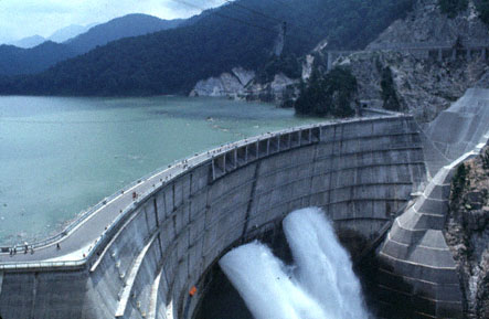
![]() In hydro power
plants the kinetic energy of falling water is captured to generate electricity.
A turbine and a generator convert the energy from the water to mechanical
and then electrical energy. The turbines and generators are installed either
in or adjacent to dams, or use pipelines (penstocks) to carry the pressured
water below the dam or diversion structure to the powerhouse. The power
capacity of a hydropower plant is primarily the function of two variables:
(1) flow rate expressed in cubic meters per second (m3/s), and (2) the
hydraulic head, which is the elevation difference the water falls in passing
through the plant. Plant design may concentrate on either of these variables
or both.
In hydro power
plants the kinetic energy of falling water is captured to generate electricity.
A turbine and a generator convert the energy from the water to mechanical
and then electrical energy. The turbines and generators are installed either
in or adjacent to dams, or use pipelines (penstocks) to carry the pressured
water below the dam or diversion structure to the powerhouse. The power
capacity of a hydropower plant is primarily the function of two variables:
(1) flow rate expressed in cubic meters per second (m3/s), and (2) the
hydraulic head, which is the elevation difference the water falls in passing
through the plant. Plant design may concentrate on either of these variables
or both.
 |
From the energy conversion point of view, hydro power is a
technology with very high efficiencies, in most cases more than double
that of conventional thermal power plants. This is due to the fact that
a volume of water that can be made to fall a vertical distance, represents
kinetic energy which can more easily be converted into the mechanical
rotary power needed to generate electricity, than caloric energies.
Equipment associated with hydropower is well developed, relatively
simple, and very reliable. Because no heat (as e.g. in combustion)
is involved, equipment has a long life and malfunctioning is rare. The
service life of an hydroelectric plant is well in excess of 50 years. Many
plants built in the twenties - the first heyday of hydroelectric power
- are still in operation.
Since all essential operating conditions can be remotely monitored and adjusted by a central control facility, few operating personnel are required on site. Experience is considerable with the operation of hydropower plants in output ranges from less than one kW up to hundreds of MW for a single unit. |
TYPES OF HYDROPOWER FACILITIES
Hydropower technology can be categorized into two types: conventional
and pumped storage. Another way of classification of hydro power plants
is according to :
![]() Rated power
capacity (big or small)
Rated power
capacity (big or small)
![]() Head of water
(low, medium and high heads)
Head of water
(low, medium and high heads)
![]() The type of
turbine used (Kaplan, Francis, Pelton etc.)
The type of
turbine used (Kaplan, Francis, Pelton etc.)
![]() The location
and type of dam, reservoir.
The location
and type of dam, reservoir.
Conventional hydropower plants use the available water energy from a river, stream, canal system, or reservoir to produce electrical energy. Conventional hydropower can be further divided between impoundment and diversion hydropower. Impoundment hydropower uses dam to store water. Water may be released either to meet changing electricity needs or to maintain a constant water level. Diversion hydropower channels a portion of the river through a canal or penstock, but may require a dam. In conventional multipurpose reservoirs and run-of-river systems, hydropower production is just one of many competing purposes for which the water resources may be used. Competing water uses include irrigation, flood control, navigation, and municipal and industrial water supply.
PUMPED STORAGE PLANTS
 |
Pumped storage hydro-electricity is a remarkably simple principle.
To start with, two reservoirs at different altitudes are required. Water
stored at height offers valuable potential energy. During periods of high
electrical demand, the water is released to the lower reservoir to generate
electricity. When the water is released, kinetic energy is created by the
discharge through high-pressure shafts which direct the water through turbines
connected to generator/motors. The turbines power the generators to create
electricity. After the generation process is complete, water is pumped
back to the upper reservoir for storage and readiness for the next cycle.
The process usually takes place overnight when electricity demand is at
its lowest.
While pumped storage facilities are net energy consumers, they are valued by a utility because they can be rapidly brought on-line to operate in a peak power production mode. This process benefits the utility by increasing the load factor and reducing the cycling of its base load units. In most cases, pumped storage plants run a full cycle every 24 hours. |
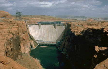
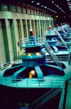
COMPONENTS OF HYDRO POWER PLANT
Most conventional hydropower plants include following major components:
![]() Dam. Controls
the flow of water and increases the elevation to create the head. The reservoir
that is formed is, in effect, stored energy.
Dam. Controls
the flow of water and increases the elevation to create the head. The reservoir
that is formed is, in effect, stored energy.
![]() Turbine. Turned
by the force of water pushing against its blades.
Turbine. Turned
by the force of water pushing against its blades.
![]() Generator.
Connects to the turbine and rotates to produce the electrical energy.
Generator.
Connects to the turbine and rotates to produce the electrical energy.
![]() Transformer.
Converts electricity from the generator to usable voltage levels.
Transformer.
Converts electricity from the generator to usable voltage levels.
![]() Transmission
lines. Conduct electricity from the hydropower plant to the electric distribution
system.
Transmission
lines. Conduct electricity from the hydropower plant to the electric distribution
system.
![]() In some hydro
power plants also another component is present penstock, which carries
water from the water source or reservoir to the turbine in a power plant.
In some hydro
power plants also another component is present penstock, which carries
water from the water source or reservoir to the turbine in a power plant.

Water turbines may be classified in different ways. One way of classification is according to the method of functioning (impulse or reaction turbine); another way is according to the design (shaft arrangement and feed of water). Water turbines may operate as turbines, as pump turbines or as a combination of both. They may be of the single regulated or double regulated type. Turbines may also be classified according to their specific speed.
Impulse turbines use a nozzle at the end of the pipeline that converts the water under pressure into a fast-moving jet. This jet is then directed at the turbine wheel (also called runner), which is designed to convert as much of the jet's kinetic energy possible into shaft power. Common impulse turbines are Pelton and cross-flow. In reaction turbines the energy of the water is converted from pressure to velocity within the guide vanes and the turbine wheel itself. Spinning of the turbine is a reaction to the action of the water squirting from the nozzles in the arms of the rotor. The typical example of reaction turbine is a Francis turbine. The advantage of small hydro power reaction turbine is that it can use the full head available at a site. An impulse turbine must be mounted above tailwater level. The advantage of impulse turbine is that it is very simple and cheap and as the water flow varies , water flow to the turbine can be easily controlled by changing nozzle size. In contrast most small reaction turbines cannot be adjusted to accommodate variable water flow.
Most hydraulic turbines consist of a shaft-mounted water-wheel or runner located within a water-passage which conducts water from a higher location (the reservoir upstream from a dam) to a lower one (the river below a dam). Some runners look very similar to a boat propeller, others have more complex shapes. The turbine runner is installed in a water passage that lets water from the reservoir flow pass the runner blades, which makes the turbine spin.
Almost all hydraulic turbine/generator units turn at a constant speed.
The constant speed one type of turbine/generator operates at may be considerably
different from the speed of another. The best speed for each type of turbine
is set during design, and a generator is then designed that will produce
usually alternating current at that speed. A device called a governor keeps
each unit operating at its proper speed by operating flow-control gates
in the water-passage. There are several types of turbine designs like Pelton,
Kaplan, Francis or cross-flow turbine.
![]()
PELTON TURBINE
 The principle
of the old water-wheel is embodied in the modern Pelton turbine. This turbine
has a similar look and physical principle like a classic water wheel. A
Pelton turbine is used in cases where large heads of water are available
(more than 40 m). The Pelton turbine is used for heads up to 2000 m. Below
250 m, mostly the Francis turbines are given preference. Today the maximum
output lies at around 200 MW.
The principle
of the old water-wheel is embodied in the modern Pelton turbine. This turbine
has a similar look and physical principle like a classic water wheel. A
Pelton turbine is used in cases where large heads of water are available
(more than 40 m). The Pelton turbine is used for heads up to 2000 m. Below
250 m, mostly the Francis turbines are given preference. Today the maximum
output lies at around 200 MW.

 |
Since then the turbine has been considerably improved in all respects
and the output of power has increased. Power is extracted from the high
velocity jet of water when it strikes the cups of the rotor (runner). There
is a maximum of 40 cup-like paddles jointed in two half-cups each water
is being squirted through nozzles onto the blades where it is deflected
by 180° and thus gives almost all of its energy to the turbine. By
the reversal almost all the kinetic energy is transferred into force of
impulse at the outer diameter of the wheel. Because of the symmetry of
the flow almost no axial force is created at the runner.
From the design point of view, adaptability exists for different flow and head. Pelton turbines can be equipped with one, two, or more nozzles for higher output. In manufacture, casting is commonly used for the rotor, materials being brass or steel. This necessitates an appropriate industrial infrastructure. Pelton turbines require only very little maintenance. |
FRANCIS TURBINE
 In the great
majority of cases (large and small water flow rates and heads) the type
of turbine employed is the Francis or radial flow turbine. The significant
difference in relation to the Pelton turbine is that Francis (and Kaplan)
turbines are of the reaction type, where the runner is completely submerged
in water, and both the pressure and the velocity of water decrease from
inlet to outlet. The water first enters the volute, which is an annular
channel surrounding the runner, and then flows between the fixed guide
vanes, which give the water the optimum direction of flow. It then enters
the runner, which is totally submerged, changes the momentum of the water,
which produces a reaction in the turbine. Water flows radially i.e., towards
the centre. The runner is provided with curved vanes upon which the
water impinges. The guide vanes are so arranged that the energy of the
water is largely converted into rotary motion and is not consumed
by eddies and other undesirable flow phenomena causing energy losses. The
guide vanes are usually adjustable so as to provide a degree of adaptability
to variations in the water flow rate and in the load of the turbine.
In the great
majority of cases (large and small water flow rates and heads) the type
of turbine employed is the Francis or radial flow turbine. The significant
difference in relation to the Pelton turbine is that Francis (and Kaplan)
turbines are of the reaction type, where the runner is completely submerged
in water, and both the pressure and the velocity of water decrease from
inlet to outlet. The water first enters the volute, which is an annular
channel surrounding the runner, and then flows between the fixed guide
vanes, which give the water the optimum direction of flow. It then enters
the runner, which is totally submerged, changes the momentum of the water,
which produces a reaction in the turbine. Water flows radially i.e., towards
the centre. The runner is provided with curved vanes upon which the
water impinges. The guide vanes are so arranged that the energy of the
water is largely converted into rotary motion and is not consumed
by eddies and other undesirable flow phenomena causing energy losses. The
guide vanes are usually adjustable so as to provide a degree of adaptability
to variations in the water flow rate and in the load of the turbine.
The guide vanes in the Francis turbine are the elements that direct
the flow of the water, just as the nozzle of the Pelton wheel does. The
water is discharged through an outlet from the centre of the turbine.
In design and manufacture, Francis turbines are much more complex
than Pelton turbines, requiring a specific design for each head/flow condition
to obtain optimum efficiency. Runner and housing are usually cast, on large
units welded housings, or cast in concrete at site, are common.
With a Francis turbine, downstream pressure can be above zero. Precautions
must be taken against water hammer with this type of turbine. Under the
emergency stop, the turbine overspeeds. One would think that more water
is going through the turbine than before the trip occurred since the turbine
is spinning faster. However, the turbine has been designed to work efficiently
at the design speed, so less water actually flows through the turbine during
overspeed. Pressure relief valves are added to prevent water hammer due
to the abrupt change of flow. Besides limiting pressure rise, the pressure
relief valve prevents the water hammer from stirring up sediment in the
pipes.
With a big variety of designs, a large head range from about 30
m up to 700 m of head can be covered. The most powerful Francis turbines
have an output of up to 800 MW and use huge amounts of water.
KAPLAN TURBINE
 For very low
heads and high flow rates a different type of turbine, the Kaplan or Propeller
turbine is usually employed. In the Kaplan turbine the water flows
through the propeller and sets the latter in rotation. In this turbine
the area through the water flows is as big as it can be the entire area
swept by the blades. For this reason Kaplan turbines are suitable for very
large volume flows and they have become usual where the head is only a
few meters.
For very low
heads and high flow rates a different type of turbine, the Kaplan or Propeller
turbine is usually employed. In the Kaplan turbine the water flows
through the propeller and sets the latter in rotation. In this turbine
the area through the water flows is as big as it can be the entire area
swept by the blades. For this reason Kaplan turbines are suitable for very
large volume flows and they have become usual where the head is only a
few meters.
 |
The water enters the turbine laterally, is deflected by the guide
vanes, and flows axially through the propeller. For this reason,
these machines are referred to as axial-flow turbines. They have
the advantage over radial-flow turbines that it is technically simpler
to vary the angle of the blades when the power demand changes what improves
the efficiency of power production.
The flow rate of the water through the turbine can be controlled by varying the distance between the guide vanes; the pitch of the propeller blades must then also be appropriately adjusted. Each setting of the guide vanes corresponds to one particular setting of the propeller blades in order to obtain high efficiency. Important feature is that the blade speed is greater than the water speed as much as twice as fast. This allows a rapid rate of rotation even with relatively low water speeds. Kaplan turbines come in a variety of designs. Their application is limited to heads from 1 m to about 30 m. Under such conditions, a relatively larger flow as compared to high head turbines is required for a given output. These turbines therefore are comparatively larger. |
CROSS-FLOW (BANKI) TURBINE
The concept of the Cross-Flow turbine -although much less
well-known than the three big names Pelton, Francis and Kaplan -is not
new. It was invented by an engineer named Michell who obtained a
patent for it in 1903. Quite independently, a Hungarian professor
with the name Donat Banki, re-invented the turbine again at the university
of Budapest. By 1920 it was quite well known in Europe, through a
series of publications. There is one single company who produces
this turbine since decades, the firm Ossberger in Bavaria, Germany. More
than 7000 such turbines are installed world-wide, most of them made
by Ossberger.
The main characteristic of the Cross-Flow turbine is the water jet
of rectangular cross-section which passes twice through the rotor
blades -arranged at the periphery of the cylindrical rotor - perpendicular
to the rotor shaft. The water flows through the blading first from
the periphery towards the centre, and then, after crossing the open space
inside the runner, from the inside outwards. Energy conversion takes
place twice; first when water falls down on the blades upon entry,
and then when water strikes the blades during exit from the runner.
The use of two working stages provides no particular advantage except
that it is a very effective and simple means of discharging the water
from the runner.
The machine is normally classified as an impulse turbine. This is
not strictly correct and is probably based on the fact that the original
design was a true constant-pressure turbine. A sufficiently large gap was
left between the nozzle and the runner, so that the jet entered the
runner without any static pressure. Modern designs are usually built with
a nozzle that covers a bigger arc of the runner periphery. With this
measure, unit flow is increased, permitting to keep turbine size
smaller. These designs work as impulse turbines only with small gate
opening, when the reduced flow does not completely fill the passages
between blades and the pressure inside the runner therefore is atmospheric.
With increased flow completely filling the passages between the blades,
there is a slight positive pressure; the turbine now works as a reaction
machine.
Cross-Flow turbines may be applied over a head range from less than
2 m to more than 100 m (Ossberger has supplied turbines for heads
up to 250 m). A large variety of flow rates may be accommodated with
a constant diameter runner, by varying the inlet and runner width.
This makes it possible to reduce the need for tooling, jigs and fixtures
in manufacture considerably. Ratios of rotor width/diameter, from
0.2 to 4.5 have been made. For wide rotors, supporting discs welded
to the shaft at equal intervals prevent the blades from bending.
A valuable feature of the Cross-Flow turbine is its relatively flat
efficiency curve, which Ossberger are further improving by using a divided
gate. This means that at reduced flow, efficiency is still quite
high, a consideration that may be more important than a higher optimum-point
efficiency of other turbines. Due to low price and good control these turbines
are, however, very successful in the area of small hydro-electric power
plants.

BIG OR SMALL HYDRO?
Hydro power plants range in capacity between few hundred watts to
more than 10.000 MW. Classification between big and small is quite common
where usually all power plants with capacity larger than 10 MW are considered
as big and all others as small. Classification among small hydro power
is also possible and terms like micro or nano hydro with capacity less
than 1 kW are also used in literature. Nevertheless it is worthwhile looking
at the specific characteristics and basic differences between big and small
power plants.
Big Hydropower
 Big
hydropower stations are of a nature that requires a good infrastructure
such as roads (during construction) and access to a big market, resulting
in long high-tension grid systems and an extensive distribution system.
It serves a great number of individual consumers and supplies power
to electricity-intensive large industry.
Big
hydropower stations are of a nature that requires a good infrastructure
such as roads (during construction) and access to a big market, resulting
in long high-tension grid systems and an extensive distribution system.
It serves a great number of individual consumers and supplies power
to electricity-intensive large industry.
Big plants are usually owned and operated by big companies or state
enterprises. The skill requirements in management, administration, operation
and maintenance are considerable. Unit cost of energy generation is
relatively low. This is due to a decrease in specific investment cost
with rising plant size, and the probability of higher load factors with
a larger number of consumers. A problem is peak demand; big numbers
of consumers tend to have their maximum individual demand during
the same time-interval, which results in a largely uncontrollable
peak of demand that must be met with increased capacity, such as
standby installations and high cost pumped-storage.
 |
From the engineering point of view, big hydro power calls for
sophisticated technology in manufacturing electro-mechanical equipment,
and high standards of feasibility studies, planning and civil construction
activities, because the risks involved are great. Long-term flow
data are a necessity and gestation periods are long. It is possible to
apply computer design technology and highly specialised fabrication
technology to achieve very high performance efficiencies that may
reach 96 % in the case of turbines. Needless to say, this process brings
about very high cost, which however may be justified because of the
large scale, where equipment cost is generally a relatively small
fraction of total cost.Big-scale hydropower stations require careful environmental
considerations. Artificial lakes may change an entire landscape and inundate
sizeable areas of arable land. Positive aspects are flood controlling
capability and the creation of new recreational sites (boating, fishing,
camping) although it is obvious that the benefits for recreation do not
rise in proportion with size.
THE CONTEXT FOR BIG HYDROPOWER STATIONS:
|
![]()
SMALL
HYDRO POWER PLANTS
 Small and micro or nano
hydropower schemes combine the advantages of large hydro on the one
hand an decentralized power supply, on the other. They do not have many
of the disadvantages, such as costly transmissions and environmental
issues in the case of large hydro, and dependence on imported fuel
and the need for highly skilled maintenance in the case of fossil fuelled
plants. Moreover, the harnessing of small hydro-resources, being of a decentralised
nature, lends itself to decentralised utilization, local implementation
and management, making rural development possible mainly based on
self-reliance and the use of natural, local resources.
Small and micro or nano
hydropower schemes combine the advantages of large hydro on the one
hand an decentralized power supply, on the other. They do not have many
of the disadvantages, such as costly transmissions and environmental
issues in the case of large hydro, and dependence on imported fuel
and the need for highly skilled maintenance in the case of fossil fuelled
plants. Moreover, the harnessing of small hydro-resources, being of a decentralised
nature, lends itself to decentralised utilization, local implementation
and management, making rural development possible mainly based on
self-reliance and the use of natural, local resources.
There are in fact many thousands of small hydro plants in operation today all over the world. Modern hydraulic turbine technology is very highly developed with the a history of more than 150 years. Sophisticated design and manufacturing technology have evolved in industrialised countries over conventional technology the last 40 years. The aim is to achieve higher and higher conversion efficiencies, which makes sense in large schemes where 1 percent more or less may mean several MW of capacity. As far as costs are concerned, such sophisticated technology tends to be very expensive. Again, it is in the big schemes where economic viability is possible. Small installations for which the sophisticated technology of large hydro is often scaled down indiscriminately, have higher capital cost per unit of installed capacity. On the other hand environmental impacts due to small hydro stations are generally negligible or are controllable because of their size. Often they are non-existent.
Small hydro power plants are in large majority connected to the electricity grids. Most of them are of the run-of-river type, meaning simply that they do not have any sizeable reservoir (i.e. water not stored behind the dam) and produce electricity when the water provided by the river flow is available but generation ceases when the river dries-up and the flow falls below a predetermined amount. Power can be supplied by a small (or micro) hydro power plant in two ways. In a battery-based system, power is generated at a level equal to the average demand and stored in batteries. Batteries can supply power as needed at levels much higher than that generated and during times of low demand the excess can be stored. If enough energy is available from the water, an alternating current (AC) direct system can generate power. This system typically requires much higher power level than the battery-based system. Small hydropower in developing countries, on the other hand, implies decentralisation. Energy produced is usually supplied to relatively few consumers nearby, mostly with a low-tension distribution network only.
Small hydro schemes have different configurations according to the
head. High head schemes are typical of mountain areas, and due to the fact
that for the same power they need a lower flow, they are usually cheaper.
Low heads schemes are typical of the valleys and do not need feeder canal.
Of the numerous factors which affect the capital cost, site selection and
basic lay-out are among the first to be considered. Adequate head and flow
are necessary requirements for hydro generation.
Most hydro power systems require a pipeline to feed water to the
turbine. The exception is a propeller machine with an open intake. The
water must pass first through a simple filter to block debris that may
clog or damage the turbine. The intake is usually placed off to the side
of the main water flow to protect it from the direct force of the water
and debris during high flow.
High safety standards in construction works are often not necessary,
even the rupture of a small dam would not usually threaten human life,
and the risks are smaller anyway if initial costs are kept down. This makes
it possible to use mainly local materials and local construction
techniques, with a high degree of local labour participation.
Small hydro systems can require more maintenance than comparable
wind or photovoltaic systems. It is important to keep debris out
of the turbine. This is done by reliable screening and construction of
a settling basin. In the turbine itself, only the bearings and brushes
will require regular maintenance and replacement.
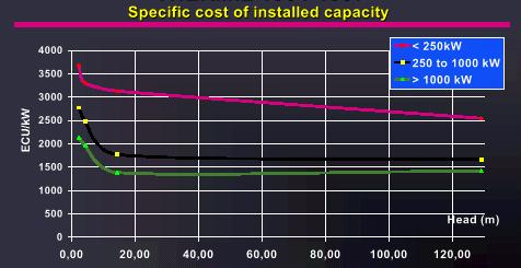
COST OF SHPP
Hydropower plants are characterised by high initial capital-investment
(according to World Bank total costs are between USD 1800 and
USD 8800 per kW for heads from 2,3 to 13,5 m and USD 1000 to
USD 3000 for heads between 27 and 350 meters.) and low operation
and maintenance cost. The investment costs include:
![]() Construction
(dam, channel, machine house),
Construction
(dam, channel, machine house),
![]() Parts for electricity
generation (turbine, generator, transformer, power lines),
Parts for electricity
generation (turbine, generator, transformer, power lines),
![]() Other
(engineering, ground property, commissioning).
Other
(engineering, ground property, commissioning).
Usually equipment for low head and low output becomes very costly
and equipment cost ranges from 40 to 50 % of total cost in conventional
hydro installations. As far as costs of civil construction-components are
concerned, no standard cost unit can be given. Dams, canals and intakes
will obviously cost a very different share of the total for different
sites. Much depends on the topography and the geology, and also on
the construction method applied and the materials used. Just to mention
some examples the total cost of new small hydro power plants in Germany
was 10-16 DM/W (5-9 ECU/W) and are divided in most cases 35% (construction)
- 50% (electricity parts) - 15% (other). There are of course some differences
between countries e.g. costs of 8 kW turbine (Banki type with regulation)
in Czech republic is 4000 USD , equivalent to 3500 ECU or 0,45 ECU/W.
The high investment costs is the largest barrier in development
of small hydro power schemes. Despite this obstacle and long pay-back times
(7-10 years in some countries e.g. Slovakia) small hydro power plants are
often cost-effective because of their long life-time (often more than 70
years) and low maintenance costs. As a general rule, total costs of operation
and maintenance without major replacements account for approximately 3
to 4% of capital costs for small and micro-hydropower installations.
THE CONTEXT FOR SMALL HYDROPOWER STATIONS
![]() Decentralised,
small power demand; small industry, individual farms and enterprises,
rural communities.
Decentralised,
small power demand; small industry, individual farms and enterprises,
rural communities.
![]() Low tension
distribution networks and eventually sub-regional micro-grid systems.
Low tension
distribution networks and eventually sub-regional micro-grid systems.
![]() Individual,
co-operative or communal ownership with semi-skilled labour requirements
and co-operative administration.
Individual,
co-operative or communal ownership with semi-skilled labour requirements
and co-operative administration.
![]() Short gestation
period with local materials and skills applicable depending on potential,
it can make a considerable impact on the quality of rural life.
Short gestation
period with local materials and skills applicable depending on potential,
it can make a considerable impact on the quality of rural life.
![]() Its flexibility
regarding adaptation to quick load variations makes it a favoured component
in any integrated power system.
Its flexibility
regarding adaptation to quick load variations makes it a favoured component
in any integrated power system.
![]() Plants can
last for very long time. Some are more than 70 years old and still in operation.
Plants commissioned recently may show even longer life span and thus can
serve consumers over several generations without polluting the atmosphere.
Plants can
last for very long time. Some are more than 70 years old and still in operation.
Plants commissioned recently may show even longer life span and thus can
serve consumers over several generations without polluting the atmosphere.
![]() Investment
in small hydro power have proved to be safe and secure over several decades.
Investment
in small hydro power have proved to be safe and secure over several decades.
![]()
SMALL HYDRO POWER PLANTS FOR
DEVELOPING COUNTRIES
 In
developing countries the domain where small hydropower can potentially
have an important impact on development is in domestic lighting and
in providing stationary motive power for such diverse productive
uses as water-pumping, wood and metal working, grain milling, textile
fibre spinning and weaving. While much of the discussion is concerned
with the generation of electricity, it must be recognised that the
same source of power can perform mechanical tasks directly via gears
and belt drives, very often more economically.
In
developing countries the domain where small hydropower can potentially
have an important impact on development is in domestic lighting and
in providing stationary motive power for such diverse productive
uses as water-pumping, wood and metal working, grain milling, textile
fibre spinning and weaving. While much of the discussion is concerned
with the generation of electricity, it must be recognised that the
same source of power can perform mechanical tasks directly via gears
and belt drives, very often more economically.
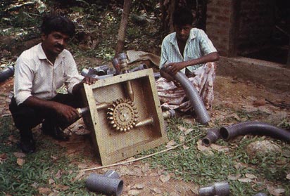
Emphasis is on the use of currently available know-how, using
simple equipment that can be made locally, and the use of local construction
materials and techniques. The aim is to reduce capital costs as far
as possible. Rather than scaling down large-scale technology, this
may lead to a more appropriate upgrading of local technology for
larger schemes at a later stage.
CHINA
The construction of small hydropower stations has been a very
meaningful in the past 25 years. Besides the development of large resources,
much emphasis was given to small-scale developments resulting in an estimated
100.000 stations around the vast countryside with installed capacity approaching
10.000 MW.
The first large-scale campaign to establish many small waterworks
started in 1956. An ambitious plan called for the construction of 1000
small stations of a multi-purpose character, combining irrigation,
flood control and power generation, in one year, reaching a total capacity
of 30 MW. Although industrial capability permitted construction of large
turbines, and the range under which small hydropower falls in China was
extended to 12 MW, this indicates that construction of very small units
continued. In fact, a range of miniature turbine-generators with outputs
from 0,6 to 12 kW was developed, suitable for scattered mountain
villages with small hydropower resources.
The development activities in this field were entirely relying on
local resources -materials, skill and labour - and the results achieved
are from this perspective even more impressive. Hydropower development
in China faces some major natural obstacles. The regional distribution
of resources is very uneven and concentrated in regions that are thinly
populated. Flow variations in many rivers are considerable. The maximum
recorded flood flow in the Huang Ho river was 88 times larger than the
minimum discharge and in smaller rivers this ratio is likely to be
much higher.
MICRO
HYDRO SYSTEMS
 Microhydro
systems are defined as hydroelectric systems that produce less than 1000
Watts. At the high end, microhydro systems produce enough power to run
three electrically efficient households. No other form of renewable energy
is so reliable or powerful for what it costs. Micro hydro system means
that the site has either very little fall or very small flow of water,
but probably not both. At sites with lower flow rates, systems are usually
tied to a battery bank and configured to produce direct current. With larger
hydro resources, systems may be configured to produce alternating current
without the use of a battery bank. These systems must be able to directly
power peak loads. In some case excess power produced is transferred to
an alternate load such as a hot water heater.
Microhydro
systems are defined as hydroelectric systems that produce less than 1000
Watts. At the high end, microhydro systems produce enough power to run
three electrically efficient households. No other form of renewable energy
is so reliable or powerful for what it costs. Micro hydro system means
that the site has either very little fall or very small flow of water,
but probably not both. At sites with lower flow rates, systems are usually
tied to a battery bank and configured to produce direct current. With larger
hydro resources, systems may be configured to produce alternating current
without the use of a battery bank. These systems must be able to directly
power peak loads. In some case excess power produced is transferred to
an alternate load such as a hot water heater.
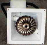
 A hydropower
turbine appropriate for household use can be bought for about USD 1000.
These simple units are about the size of a breadbox and use a rewired automobile
alternator to produce direct current. The direct current is used to charge
batteries, then converted to AC power with an inverter.
A hydropower
turbine appropriate for household use can be bought for about USD 1000.
These simple units are about the size of a breadbox and use a rewired automobile
alternator to produce direct current. The direct current is used to charge
batteries, then converted to AC power with an inverter.
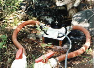
A typical micro hydro installation diverts a small portion of stream flow across a screen into a water storage e.g. 200 litre drum. The drum acts as a settling basin and the screen collects debris from the water which may clog the intake to the turbine. The water flows from the drum to the turbine through PVC piping (usually 5 to 10 centimetres in diameter), and then returns to the stream. Additional costs for piping, controls, batteries, and wiring vary depending on the particular application, but range from USD 1000 to USD 5000.
 Micro hydro
turbines come in two basic forms. One uses an alternator, just like an
automobile. The other (nano hydro systems) uses a permanent magnet (permag)
generator/motor. The alternator based machines are for larger systems producing
from 100 to 1000 watts, while the permag units are best suited to systems
producing under 80 Watts.
Micro hydro
turbines come in two basic forms. One uses an alternator, just like an
automobile. The other (nano hydro systems) uses a permanent magnet (permag)
generator/motor. The alternator based machines are for larger systems producing
from 100 to 1000 watts, while the permag units are best suited to systems
producing under 80 Watts.
Larger systems use shunt diversion for regulation. This prevents
overspeeding of the turbine and premature wear of parts. Smaller systems
use regulation schemes that unload the alternator when power is not needed.
In all cases, these controls need to be user adjustable. Micro hydro systems
are easy to fit with batteries. The turbine produces constant power all
the time. The battery acts as a flywheel to smooth out the inevitable
peaks of consumption. Micro hydros refill the batteries almost immediately
after even a little power is consumed from the battery. These systems are
shallow-cycling and ordinary batteries will last a long time. Usually
spending money on good pipe and an efficient turbine is more effective
than spending it on batteries. In a microhydro system the length and diameter
of the pipe must be specified to suit the situation and the turbine. Using
long runs of small diameter pipe will make even the finest turbine ineffective.

NANOHYDRO - PERMAG
 |
What sets nano hydro systems apart from other hydro generators is the use of permanent magnet generators for the power source. The advantage to this is that no power is fed back into the machine to electrically generate a magnetic field, as is the case with most alternators, so all of what is produced will feed the batteries. The disadvantage of a permag set-up is that the maximum output is limited by the inherent strength of the magnets. Normally that's not a problem in a nano hydro situation because usually flow and head of water are too small for a larger, more powerful system anyway. |
BATTERY-BASED SYSTEMS
Most micro and nano hydro systems are battery-based. They require
far less water than AC systems and are usually less expensive. Because
the energy is stored in batteries, the generator can be shut down without
interrupting the power delivered to the loads. Since only the average load
needs to be generated in this system, the pipeline, turbine, generator
and other components can be much smaller than those in AC system. For conversion
of DC battery power to AC output (type of power needed by most of home
appliances) inverters are used. The input voltage to the batteries in battery-based
system usually ranges from 12 to 48 Volts DC. If the transmission distance
is not long then 12 V system is used. For longer transmission distances
higher voltage is used.
![]()
AC SYSTEMS
Alternating current (AC) hydro power systems are those used by utilities,
but it can also be used on a home power scale under the appropriate conditions.
In home power scale system power is not sent to the utility grid, but is
directly used by a homeowners appliances (load). AC system does not need
batteries. This means that the generator must be capable of supplying the
continuous demand, including the peak load. The most difficult load is
the short-lasting power surge drawn by motors in refrigerators, washing
machines and some other appliances. Usually in typical AC system, an electronic
controller is keeping voltage and frequency within prescribed limits. The
output from hydro power plan can not be stored and any unused power is
sent to a shunt load, which can be e.g. a hot water heater. There is
almost always enough excess power from this type of system to heat domestic
hot water and provide space heating as well.
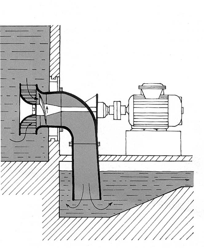
PUMP AS TURBINE
High costs of equipment and civil works, or more generally, the
capital-intensive nature of small hydropower plants, has long been a major
constraint. However, in many situations it is necessary not only to achieve
a better relation of costs compared to other energies, but to reduce them
in absolute terms. This is possible to some degree by standardising equipment,
but the scope for using such standardised equipment remains limited since
no two sites are exactly the same. Efforts at cost reduction through indigenous
manufacture are more promising, largely due to much lower labour costs.
To make this possible, standards of design, performance and sometimes reliability
must be lowered and all unnecessary sophistication avoided. The same is
true in civil construction work, where local materials and techniques should
be used to the largest possible extent.
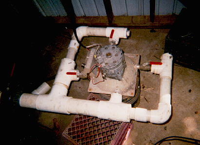
In developing countries and especially in rural areas, it is generally recognized that small hydropower may play a significant role. However, high initial investment costs of small hydropower plants have restricted rapid development of this energy potential in many countries. The use of standard pumps as turbines (PAT) may often be an alternative with a considerable economic advantage and might therefore contribute to a broader application of micro-hydropower. Direct drive of machinery, electricity generation (in parallel to a large grid or isolated) or combinations of these are possible just as with a conventional turbine. The only difference is that a PAT cannot make use of the available water as efficiently as a turbine due to its lack of hydraulic controls.
FIELDS OF APPLICATION OF PUMPS
USED AS TURBINES
Pumps (rotational fluid machines) are completely reversible and
can run effectively as a turbine. Standard pumps not intentionally designed
to operate as turbines are now more and more used in small and micro-hydropower
schemes due to their advantages mentioned above. However, performance in
both modes are not identical although the theory of ideal fluids would
predict the same. Without exception, the optimum flow and head in the turbine
mode is greater than in pumping mode. The main reason for this difference
is related to the hydraulic losses of the machine.
Applications of PAT range from direct drive of machinery in agro-processing
factories and small industries (flour mills, oil expellers, rice hullers,
saw mills, wood and metal workshops) to electricity generation both in
stand-alone and grid-linked stations.
In most instances, no design changes or modifications need to be
made for a pump operating as a turbine provided that selection has taken
into account the higher operating head and power output of the machine
in turbine mode and consequently, nominal turbine speed has been taken
well below maximum permissible pump speed. However, a design review is
also required to check any adverse effects occurring from the reverse rotation
in turbine mode.
Advantages of PAT
![]() the investment
costs of PATs may be less than 50% of those of a comparable turbine (especially
for small units below 50 kW). This might be an important issue for projects
with limited budgets and loan possibilities
the investment
costs of PATs may be less than 50% of those of a comparable turbine (especially
for small units below 50 kW). This might be an important issue for projects
with limited budgets and loan possibilities
![]() construction:
the absence of a flow control device, usually felt as a drawback, is at
the same time an advantage since the pump construction is usually simple
and sturdy
construction:
the absence of a flow control device, usually felt as a drawback, is at
the same time an advantage since the pump construction is usually simple
and sturdy
![]() availability:
due to their widespread application (irrigation, industry, water supply),
standard pumps are readily available (short delivery times) and manufacturers
and their representatives are world-wide present
availability:
due to their widespread application (irrigation, industry, water supply),
standard pumps are readily available (short delivery times) and manufacturers
and their representatives are world-wide present
![]() spare parts:
spare parts are readily available since major pump manufacturers offer
after- sales services almost throughout the world
spare parts:
spare parts are readily available since major pump manufacturers offer
after- sales services almost throughout the world
![]() maintenance:
no special equipment and skills are required.
maintenance:
no special equipment and skills are required.
Disadvantages
![]() No hydraulic
control device: therefore, a control valve must be incorporated in the
penstock line (additional costs) to start and stop the PAT. If the valve
is used to accommodate to seasonal variations of flow, the hydraulic losses
of the installation will increase sharply.
No hydraulic
control device: therefore, a control valve must be incorporated in the
penstock line (additional costs) to start and stop the PAT. If the valve
is used to accommodate to seasonal variations of flow, the hydraulic losses
of the installation will increase sharply.
![]() Lower efficiency
at part load: a conventional turbine has an effective hydraulic control
(adjustable guide vanes, nozzles or runner blades) to adjust the machine
to the available flow or the required output. If PATs are operated at other
than the design flow, i.e. below their best efficiency point a relatively
rapid drop of efficiency will occur.
Lower efficiency
at part load: a conventional turbine has an effective hydraulic control
(adjustable guide vanes, nozzles or runner blades) to adjust the machine
to the available flow or the required output. If PATs are operated at other
than the design flow, i.e. below their best efficiency point a relatively
rapid drop of efficiency will occur.
The disadvantages of PATs can be reduced to a minimum if the PAT
is very carefully selected and only applied where justified. Poor performance
due to an inappropriately selected machine or application will lead to
a reduction of gains. Summed up over the entire lifetime of the machine,
this reduced output might by far offset the cost advantage of the PAT (lower
investment costs) in comparison to a conventional turbine.
![]()
DIFFERENCES BETWEEN PUMPS
AND TURBINES
Pumps are usually operated with constant speed, head and flow. A
pump is therefore designed for one particular of operation (duty point)
and does not require a regulating device (guide vane). Ideally, the duty
point coincides with the maximum efficiency of the pump.
Turbines operate under variable head and flow conditions.
In an small hydro power plant, flow must be adjustable to either accommodate
to seasonal variations of the available water or to adjust power output
according to the demand of the consumers. Adjustable guide vanes and/or
runner blades (or nozzles controlled by a streamlined valve) regulate the
flow.
TYPE OF PUMP TO BE USED AND EFFICIENCY
IN TURBINE MODE
Virtually any type of pump may be used as turbine. However, the
main advantage of a PAT, i.e. lower costs than a conventional turbine,
is very pronounced for standard centrifugal and mixed flow pumps whereas
axial flow pumps are less advantageous in that respect. The vast field
of different pump designs and power ranges provides a suitable PAT for
almost any application with heads from about 10 m up to several hundred
meters. Large flows may be accommodated with double-flow pumps. Even submersible
pumps may be used as PATs which, when integrated in the water course or
pipe system, are completely hidden away underground, an important factor
for the conservation of the environment. Efficiencies of pumps used as
turbines may be the same as in pump mode but are more often several percent
(3 - 5%) lower.
Direct drive of machinery, electricity generation (in parallel to a large grid or isolated system) or combinations of these are possible just as with a conventional turbine. Although the PATs cover a wide range of the small hydropower domain, they cannot replace conventional turbines everywhere. Since PATs have no hydraulic control device such as guide vanes, they are usually unsuitable to accommodate variable flow conditions. Throttling flow by means of a control valve in the penstock is inefficient and only applicable over a small range.
The lack of a hydraulic control device of a PAT has long been seen as a disadvantage also in terms of constancy of PAT speed under variable load. Grid-linked electricity generation or direct drive of machinery are either constant load applications or do not require precise speed control. These applications are therefore very suitable for PATs. Stand alone electricity generation on the other hand requires some form of governing to keep voltage and frequency within acceptable limits under changing load. The use of PATs in free-standing electricity generation is, however, not excluded due to the recent development of electronic load controllers which provide effective governing in conjunction with both induction and synchronous generators. Electronic load controllers keep the load on the PAT constant by switching in ballast loads whenever the electricity demand of the consumers drops.
HYDRO RAM PUMP
Hydro ram is not an animal but a self-driven pump first installed
at the turn of the century when they were popular with farmers who had
natural water courses on their land. With the coming of grid electricity
and mains water, many rams were left to rot and rust in the post-war period.
Nevertheless this device is a useful source of cheap energy even today.
Ram pumps do not produce electricity but the mechanical work for pumping
water to higher elevations. They use a downhill water pressure to pump
a portion of that water higher uphill to a holding tank. No other
source of power is needed. The hydro rams are complete in themselves and
designed to work with the minimum of attention, and to suit all the ordinary
conditions.
The hydro ram has proved to be one of the most reliable devices
used for water pumping. Many over 100 years old are still in use, and it
remains one of the few really practical and efficient uses of renewable
energy today. Hydro rams are relatively cheap, will last almost indefinitely
and with no moving metal parts and its simplicity require only minimum
of maintenance. If the two essentials are provided a supply of water
(spring or stream, as little as 4 litres per minute will suffice) and the
ability to provide a fall for that water the hydro ram can reduce or
even eliminate costly water bills. Typical uses of hydro rams include :
![]() Village water
supplies
Village water
supplies
![]() Irrigation
Irrigation
![]() Water pumping
and circulation in industry
Water pumping
and circulation in industry
![]() Water circulation
for heat pumps
Water circulation
for heat pumps
![]() Water circulation
for solar panels
Water circulation
for solar panels
How a Ram Pump Works
All ram pumps work on the principle of momentum which is controlled
by a cycle set up by the interaction of two valves in the pump. The water,
being admitted into the drive pipe, flows through it by gravitation until
it reaches the ram, passes through the ram and through the pulse valve
into the waste drain. As the water flows, its velocity increases until
the pulse valve is no longer able to pass the volume of water flowing,
and on this point being reached the pulse valve is suddenly closed. The
outlet thus being closed, the flow of water suddenly stops. This produces
a concussion of more or less severity in the body of the ram, according
to the height and distance from which the water is flowing, and a result
of this concussion is that a portion of the water in the body of the ram
is forced upwards through the delivery valve into the air cylinder. At
the same time the recoil allows the pulse valve to return to its original
position. The outlet being thus reopened, the water which was brought to
rest by the closing of the pulse valve recommences to flow through the
ram till it acquires the necessary velocity to raise the pulse valve a
second time , closing the outlet, producing a concussion, and forcing more
water into the air chamber through the delivery valve. This series of events
occurs from 40 to 90 times per minute, according to the size of the hydro
ram, fall of water driving ram, etc. The ram will continue working automatically
for months, the pulse valve rubber and the delivery valve rubber being
the only moving parts.
The water, which is forced into the air chamber, finds its way from
it through a pipe, known as the rising main or delivery pipe, to the place
where it is required for use, a continuous flow being maintained so long
as the ram remains working.
The fall of water necessary to work a ram may be as low as 0,5 meter
and with such a fall, water may be raised to 10 to 15 meters. With higher
falls, such as from 2 to 10 meters and over, water can be raised to upwards
of 100 meters in height and more than 1 kilometre in distance.
The installation is extremely simple. All that is required water
at the point of by constructing a pool. From this running downwards on
an even gradient to the point of location of the ram itself, runs the drain
pipe which has to be heavy gauge galvanised steel or cast iron pipe and
of appropriate length which is dependent upon the height to which the water
is to be pumped. Although it is not essential that this pipe should be
buried, it is preferable in order to avoid interference from wild life
and unauthorised persons. The ram chamber itself can vary considerably
but all that is required is a concrete base which securely hold the ram
in place. Hydro rams are working unaffected by the temperature changes
(especially low temperatures which might cause a conventional system to
freeze unless some form of heat is provided.)
![]()
GUIDELINES
FOR SMALL HYDRO POWER PLANTS PLANNING
Many people have access to some form of running water and do not
know how much power, if any, can be produced from it. Almost any house
site has solar electric potential (photovoltaic). Many sites also have
some wind power available. But water power depends on more than the presence
of water alone. A lake or well has no power potential. The water must be
flowing. In construction of small or micro hydro system many factors determine
the feasibility of such a system. These include:
![]() the amount
of power available from the stream, and if it is sufficient to meet power
requirements;
the amount
of power available from the stream, and if it is sufficient to meet power
requirements;
![]() legal restrictions-local
or state, on the development of the hydroelectric site, and the use of
the water;
legal restrictions-local
or state, on the development of the hydroelectric site, and the use of
the water;
![]() the availability
of turbines and generators of the type or capacity required;
the availability
of turbines and generators of the type or capacity required;
![]() the cost of
developing the site and operating the system; and
the cost of
developing the site and operating the system; and
![]() the rate a
utility will pay for electricity you generate (if you connect to their
system).
the rate a
utility will pay for electricity you generate (if you connect to their
system).
Principal question is: do I have a site suitable for hydroelectric
power production? To answer that question, we have to examine four factors.
![]() The distance
of head or vertical fall that the water source develops.
The distance
of head or vertical fall that the water source develops.
![]() The amount
of water available for generation.
The amount
of water available for generation.
![]() The length
of pipe needed to go from the water source to the hydropower plant.
The length
of pipe needed to go from the water source to the hydropower plant.
![]() The distance
from the hydropower plant to the electrical load, whether that be storage
batteries, or in the case of AC generation, the appliances themselves.
The distance
from the hydropower plant to the electrical load, whether that be storage
batteries, or in the case of AC generation, the appliances themselves.
Given these four factors, we can determine not only if hydroelectric power generation is feasible, but which diameter of pipe is needed, which type of the available hydroplants to use, and approximate output and costs.
The first step in assessing the feasibility of any hydroelectric
system is to determine the amount of power that you can obtain from the
stream at your site. The power available at any place is primarily a product
of the flow and head. Flow is amount of water flowing through the turbine
and is typically measured in cubic meters per second m3/s or in cubic
feet per second cfs or gallons per minute GPM are used.
Head is a measure of the pressure of falling water available at
turbine expressed in meter water column. This pressure is a function of
the vertical distance that water drops and the characteristics of the channel,
or pipe, through which it flows. It must be distinguished between gross
head, which is the difference of elevation between the water surface of
the forebay and the tail race and net head, which is the actual pressure
available at the turbine. To obtain net head, allowances must be made for
losses in the penstock and draft tube. Gross head can be determined by
a topographical survey using levels and tape measures. Head is expressed
in meters (or in feet in the USA). High flow and/or head means more available
power. The higher the head the better, because less water is necessary
to produce a given amount of power, and smaller, more efficient, and less
costly turbines and piping can be used.
Hydroelectric sites are broadly categorized as low or high head.
Low head typically refers to a change in elevation of less than 3 meters.
A vertical drop of less than 0,6 meters will probably make a hydroelectric
system unfeasible. A high flow rate can compensate for low head, but a
larger, and more costly turbine will be necessary. It may be difficult
to find a turbine that will operate efficiently under very low heads and
low flow.
CONFIGURATION OF SMALL HYDRO
POWER PLANTS
Small hydro turbines can be configured to operate efficiently at
sites with a wide range of head and flow rates. In case of micro hydro
systems with batteries the greater predictability of hydro resources can
help reduce the size of other system components like battery banks. Battery
banks for PV systems are usually sized to provide five days of cloudy-day
power, while small hydro systems usually need only one or two days of storage.
It is responsible to assess a hydro resource during both wet and dry seasons.
It is the responsibility of anyone who uses a hydro resource to evaluate
the effects that water diversion may have on the ecology of the waterway
and understand any applicable regulatory or legal restrictions. A rule
of thumb used by some hydro builders is to divert 10 percent or less of
the stream's minimum flow. Note that use, access to, control, or diversion
of water flows is highly regulated in many countries. So is any physical
alteration of a stream channel or bank that may effect water quality or
wildlife habitat, regardless of whether or not the stream is on private
property.
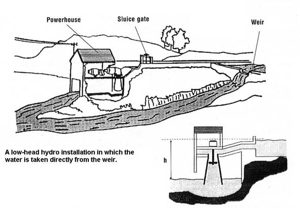
Determining Head
 When determining
head (fall), you must consider both gross or static head, and net or
dynamic head. Gross head is the vertical distance between the top of
the penstock (the piping that conveys water, under pressure, to the turbine)
and the point where the water discharges from the turbine. Net head is
gross head minus the pressure or head losses due to friction and turbulence
in the penstock. These head losses depend on the type, diameter, and length
of the penstock piping, and the number of bends or elbows. You can use
gross head to approximate power availability and determine general feasibility,
but you must use net head to calculate the actual power available. There
are several ways to determine gross head. The most accurate technique is
to have a professional survey the site. If you know that you have an elevation
drop of several dozens meters, a less expensive, but less accurate technique
is to use an aircraft altimeter. In some countries it is possible to buy,
borrow, or rent an altimeter from a small airport or flying club. You will
have to account for the effects of barometric pressure and calibrate the
altimeter as necessary. Another option is to use the hose/tube method
described below.
When determining
head (fall), you must consider both gross or static head, and net or
dynamic head. Gross head is the vertical distance between the top of
the penstock (the piping that conveys water, under pressure, to the turbine)
and the point where the water discharges from the turbine. Net head is
gross head minus the pressure or head losses due to friction and turbulence
in the penstock. These head losses depend on the type, diameter, and length
of the penstock piping, and the number of bends or elbows. You can use
gross head to approximate power availability and determine general feasibility,
but you must use net head to calculate the actual power available. There
are several ways to determine gross head. The most accurate technique is
to have a professional survey the site. If you know that you have an elevation
drop of several dozens meters, a less expensive, but less accurate technique
is to use an aircraft altimeter. In some countries it is possible to buy,
borrow, or rent an altimeter from a small airport or flying club. You will
have to account for the effects of barometric pressure and calibrate the
altimeter as necessary. Another option is to use the hose/tube method
described below.
Whatever method you use, you will need to determine the vertical
distance between the point where water will enter the penstock and the
point where water will discharge from the turbine. Always be safety-conscious
when working near or in a stream, especially in narrow or steep stream
channels and fast flowing water. Never work alone. Never wade into water
in which you cannot see the bottom and without first testing the depth
with a stick.
To perform the hose/tube method you will need an assistant, 6
to 9 meter length of small-diameter garden hose or other flexible tubing,
a funnel, and a yardstick or measuring tape. Begin by stretching the hose
or tubing down the stream channel from the point that you have decided
is the most practical elevation for the penstock intake. Have your helper
hold the upstream end of the hose, with the funnel in it, under the water
as near the surface as possible. While he/she does this, lift the downstream
end until water stops flowing from it. Measure the vertical distance between
your end of the tube and the surface of the water. This is the gross head
for the section of stream between you and your helper. Have your assistant
move to where you are and place the funnel at the same point where you
took your measurement. Then walk downstream, and repeat the procedure.
Continue taking measurements until you reach the point where you plan to
site the turbine. The sum of these measurements will give you a rough approximation
of the gross head for your site. Note that, due to the force of the water
into the upstream end the hose, water may continue to move through the
hose after both ends of the hose are actually level. You may subtract few
centimetres from each measurement to account for this. It is best to be
conservative in these preliminary head measurements.
![]()
Determining Water Flow
Environmental and climatic factors, as well as human activities
in the watershed, determine the amount and characteristics of stream flow
on a day-to-day and seasonal basis. A storage reservoir can control flow,
but unless a dam already exists, building one can greatly increase cost
and legal complications. You may be able to obtain stream flow data from
the local offices, from the local engineer, or local water supply or flood
control authorities. If you cannot obtain existing flow data for your stream,
you will need to do a site survey. Generally, unless you are considering
a storage reservoir, you should use the lowest average flow of the year
as the basis of the system design. Alternatively, you can use the average
flow during the period of highest expected electricity demand. This may
or may not coincide with lowest flows. There may be legal restrictions
on the amount of water that you can divert from a stream at certain times
of the year. In such a case, you will have to use this amount of available
flow as the basis of design.
Measuring flow is a little more difficult. This should probably be done in more than one place too. This is because most streams pick up water as they go. Therefore choosing the best spot for your system requires careful consideration of several things. There are several ways to measure flow; here are two. In both cases, the brook water must all pass through either a pipe or a weir. A common method for measuring flow on very small streams is the bucket method. This involves damming the stream with logs or boards to divert the stream flow into a bucket or container. This method is the easiest way of measuring flow for streams with up to 5 litres per second or so, which accounts for most small hydro sites by far. You'll need to construct a temporary dam of sorts at the water source. Than fit a short length of pipe large enough to handle all the water you plan to use for generation into the dam. Using a bucket of known capacity and a stopwatch you will have to estimate the time - how long it takes to fill the bucket. Repeat several times to determine that your technique is accurate. The rate that the container fills is the flow rate. For example, 20 litre bucket that fills in one minute is a flow rate of 20 litres per minute.
You can also try the following method to roughly estimate the flow in streams where it is impractical to attempt the bucket method. This method involves wading across the stream channel. Do not try this method if the stream is fast-flowing and over your calves! You could lose your footing, be swept downstream, and possibly drown. Never wade into any stream in which you cannot see the bottom! Always check the depth and character of the stream bed with your stick before you take a step. To perform this method, you will need an assistant, a tape measure, a yardstick or calibrated measuring rod, a weighted float (a plastic bottle half filled with water to give a better estimate of flow velocity), a stopwatch, and some graph paper. Begin by calculating the cross-sectional area of the stream bed during the time of lowest water flow. To do so, select a stretch of the stream with the straightest channel and most uniform depth and width as possible. At the narrowest point of this stretch, measure the width of the stream. Then, with the yardstick, walk across the stream and measure the water depth at 30 centimetres increments across the stream. Be sure to keep the measuring stick as vertical as possible. You may want to stretch a string or rope across the stream with the increments marked on it to assist in this process. Plot these depths on a piece of graph paper. This will give you a cross-sectional profile of the stream. Determine the area of each block or section of the stream by calculating the areas of the rectangles and triangles in each section. (Area of a rectangle = length x width; area of a triangle = ½ base x height). Add the areas of all the blocks together for the total area.
Next, determine the flow velocity. From the point where you measured the width, mark a point at least 10 meters upstream, and release the weighted float in the middle of the stream. Carefully record the time it takes the float to pass between the two points. Make sure that the float does not hit or drag on the bottom of the stream. If it does, use a smaller float. Divide the distance between the two points by the float time in seconds to get flow velocity in meters per second. Repeat this procedure several times to get an average value. The more times you do so, the more accurate your estimate will be. If the float gets hung up or stalls, start over, or this will throw the average off. Multiply the average velocity by the cross-sectional area of the stream. Multiply this value by a factor that accounts for the roughness of the stream channel (0.8 for a sandy stream bed, 0.7 for a bed with small to medium sized stones, and 0.6 for a bed with many large stones). The result will be the flow rate in cubic meters per second.
Keep in mind that this value will be the flow at the time of measurement.
You should repeat the procedure several times during the low flow season
to more accurately estimate the average low water flow. You do not have
to measure the water depth each time. You can simply measure the water
depth above, or below, the water level when you first measured the stream,
and calculate the area of greater or less water, and add or subtract this
from the baseline area. Alternatively, you may be able to install a gauge
(made from a calibrated rod or post) on the bank so that you can easily
read the water depth and calculate the cross-sectional area of the stream.
You will need to repeat the flow velocity procedure each time, however.
You may be able to correlate your survey data with long term precipitation
data for your area, or flow data from nearby rivers, to get an estimate
of long-term, seasonal low, high, and average flows for your stream. Remember
that, no matter what the volume of the flow is at any one time, you may
be able to legally divert only a certain amount or percentage of the flow.
Also try to determine if there any plans for development or changes in
land use upstream from your site. Activities such as logging can greatly
alter stream flows.
LOSSES IN PIPELINE SYSTEMS
In real fluid flows, losses occur due to the resistance of the pipe
walls and the fittings to this flow and lead to an irreversible transformation
of the energy of the flowing fluid into heat. Two forms of losses can be
distinguished: losses due to friction and local losses.
Losses due to friction originate in the shear stresses between adjacent
layers of water gliding along each other at different speed. The very thin
layer of water adhering the pipe wall does obviously not move while the
velocity of every concentric layer increases to reach maximum velocity
at the centre-line of the pipe. If the fluid particles move along smooth
layers, the flow is called laminar or viscous and shear stresses between
the layers dominate. In engineering practice however, the flow in a pipeline
is usually turbulent, i.e. the particles move in irregular paths and changing
velocities. It is important to use pipelines of sufficient diameter to
minimise friction losses from the moving water. When possible the pipeline
should be buried. This stabilises the pipe.
Local losses occur at changes of cross sections, at valves and at
bends. These losses are sometimes referred to as minor losses since in
long pipelines their effect may be small in relation to the friction loss.
![]()
Determining Power
At most sites, what is called run of river is the best mode of operation.
This means that power is produced at a constant rate according to the amount
of water available. Usually the power is generated as electricity and can
be eventually stored in batteries. The power can take other forms: shaft
power for a saw, pump, grinder, etc. Both head and flow are necessary to
produce power. Even a few litres per second can be useful if there is sufficient
head. Since power = Head x Flow, the more you have of either, the more
power is available.
To calculate available power, head losses due to friction of flow
in conduits and the conversion efficiency of machines employed must also
be considered. The simple formula for potential power output is following:
Power (kW) = Head (metres) x Flow (m3/second) x Gravity (9,81) x Efficiency (0,6)
Head = Net head = Gross head -losses (m)
Here the overall efficiency was set at 60%.
For small outputs of interest here, and as a first approximation, the formula can be simplified:
Power(kW)= Head (m) x Flow (litres/second)/200
Here the overall efficiency of 50 % is implied. The rule of thumb calculation is therefore on the conservative side.
For the US units a simple rule of thumb to estimate your power is :
Power (Watts) = Head (feet) x Flow (gpm) /10
Keep in mind this is power that is produced 24 hours a day. So 100
W in hydro power plant is equivalent to a PV system of 400-500 watts if
the sun shines every day. Of course, the water may not run year round either.
The efficiencies (including turbine and generator efficiencies),
which were chosen in above mentioned equations between 50-60 %, depend
on make and operating conditions (head and flow). Generally, low head,
low speed water wheels are less efficient than high head, high speed turbines.
The overall efficiency of a system can range between 40% and 70%. A well-designed
system will achieve an average efficiency of 75%. Turbine manufacturers
should be able to provide a close estimate of potential power output for
their turbine, given the head and flow conditions at your site. There will
also be line losses in any power lines used to transmit the electricity
from the generator to the site of use.
A turbine/generator that produces 500 watts continuously (12 kWh per day), and includes batteries for power storage, will be sufficient to meet the power requirements of a small house for lighting, entertainment, a refrigerator, and other kitchen appliances. Remember that using energy conservatively in energy-efficient appliances can reduce energy requirements significantly.
Estimation of annual electricity production E:
E (kWh) = Power (kW) x Time (hours)
|
In a typical small hydro power plant every litre per second (0.001 m3/s) of water falling down from 1 meter height can produce 20 - 30 kWh of electricity per year. |
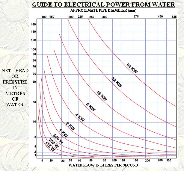
Conversion Factors
Here are some of the conversion factors you may need when evaluating
a hydro power site:
1 cubic foot (cf) = 7,48 gallons;
1 cubic foot per second (cfs) = 448,8 gallons per minute (gpm);
1 inch = 2,54 centimetres; 1 foot = 0,3048 meters;
1 meter = 3,28 feet; 1 cf = 0,028 cubic meters (cm); 1 m3 = 35,3
cf;
1 gallon = 3,785 litres; 1 cf = 28.31 litres; 1 cfs = 1698,7 litres
per minute;
1 cubic meter per second (m3 /s) = 15842 gpm;
1 pound per square inch (psi) of pressure = 2,31 feet (head) of
water;
1 pound (lb) = 0,454 kilograms (kg);
1 kg = 2,205 lbs;
1 kilowatt (kW) = 1,34 horsepower (hp); 1 hp = 746 Watts.
![]()
OCEAN POWER
 The oceans have long
been recognized as a potential source of energy. The ocean's motion carries
energy in the form of tides, currents, and waves. In principle, some of
this energy could be used to perform work and to produce electricity.
The oceans have long
been recognized as a potential source of energy. The ocean's motion carries
energy in the form of tides, currents, and waves. In principle, some of
this energy could be used to perform work and to produce electricity.
TIDAL
POWER
Tidal energy differs from all other energy sources in that the energy
is extracted from the potential and kinetic energies of the earth-moon-sun
system. The well known ocean tides result from this interaction, producing
variations in ocean water levels along the shores of all continents. As
the water level fluctuates twice daily through this range, it alternately
fills and empties natural basins along the shoreline, suggesting that the
currents flowing in and out of these basins could be used to drive water
turbines connected to generators and thus to produce electricity. The higher
the tides, the more electricity can be generated from a given site, and
the lower the cost of electricity produced. The technology employing this
energy source is very similar to that of low head hydropower.
POTENTIAL
World-wide, approximately 3000 GW of energy is continuously available
from the action of tides. Experts estimated that only 2% (60 GW), what
is about 50 times less than the world's potential of hydroelectric power
capacity, can potentially be recovered from tides for electricity generation.
Currently, only in places with large tidal range (greater than 5 meters)
can tidal power be extracted economically.
In some places of the world tidal energy is quite attractive. For
coastal areas, usually at the entrances to large estuaries, resonance can
occur, leading to far greater than average tidal ranges which could relatively
conveniently be blocked off. Such circumstances are found e.g. in Canada,
with a mean tidal range of 10,8 metres or in the Severn Estuary in Britain
with a mean range of 8,8 metres, making large scale projects at both these
locations economical.
DEVELOPMENT
Over the past forty years, there has been constant interest in harnessing
tidal power. Initially, this interest focused on estuaries, where large
volumes of water pass through narrow channels generating high current velocities.
Engineers felt that blocking estuaries with a barrage and forcing water
through turbines would be an effective way to generate electricity. From
an engineering point of view they were right. But, increasingly the environmental
costs of such a design became clear.
There are three commercial-scale tidal power plants (barrages) in operation: a 240 MW plant which was completed on the estuary of the La Rance River near St. Malo, France in 1967, a 1MW plant on the White Sea in Russia completed in 1969 and a 16 MW plant in Nova Scotia, Canada. The environmental problems have prevented further development of the barrage technology.
Tidal power plant in La Rance.
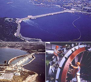
TECHNOLOGY
Tidal power is a proven technology: it has been used for centuries
in small mill-type applications where natural conditions make it possible.
Tidal energy can be converted into electrical energy in several ways. Conventional
systems such as barrages (or low dams) store water in inlets from high
tides for release through hydraulic turbines during lower tides. The newest
technology which converts tidal or coastal currents to power seems to be
very promising because it is less environmentally destructive.
The usual technique (referred to as barrage technology) is to dam
a tidally-effected estuary or inlet, allowing the tidal flow to build up
on the ocean side of the dam and then generating power during the few hour
high tide period. In this way it is functioning in La Rance. After the
water level reaches maximum high tide, gate valves are closed and the water
is impounded and awaits low tide when it is released and produces power.
The gates can be opened or closed in sequence with the tides permitting
water flow only when there is sufficient head to power the turbines. The
basic technology of power production is similar to that for low head hydro
power plants what means that the head drives the water through the turbine
generators. The main difference, apart from the salt water environment,
is that the turbines in tidal barrages have to deal with regularly varying
heads of water. The turbines are designed so that the flow of water both
into and out of the basin produces electricity. Because of the intermittent
nature of this flow, the effective duty factor of such an installation
is less than 100%. A tidal power station produces only about one third
as much electrical energy as would a hydroelectric power plant of the same
peak capacity operating continuously. Tidal barrages are effectively fences
which completely block a estuary channel.
![]()
ENVIRONMENT
The barrage does not easily scale up to modern commercial levels
of output capacity. By increasing the size of the pond one increases the
four major negative environmental impacts of the barrage technology: navigation
is blocked, fish migration is impeded and fish are killed by passing through
the turbines, the location and nature of the intertidal zone are changed,
and the tidal regime is changed downstream. Reduced tidal range would destroy
much of the habitat used by wading birds, fish (such as salmon) would be
unable to travel upstream to breed, and sediment trapped behind the barrage
could quickly reduce the volume of the estuary. It seems that while there
are few environmental impacts associated with a smaller tidal facility,
(i.e., no siltation, no negative impacts to water tables, fisheries or
fish migration), larger operations could potentially limit fish and mammal
passage and change tidal ranges, thereby effecting salt water intrusion
into local tributary streams and impacting salmon spawning.
TIDAL TURBINES
By the early 1990s, interest in estuarine-derived tidal power had
declined, and scientists and engineers began to look at the potential of
coastal currents which can be harnessed by tidal turbines. Instead of using
costly barrages and low head turbines located in estuaries, it may be possible
to harness the kinetic energy of the tides in fast tidal currents or streams
at suitable sites, using relatively simple techniques - tidal turbines.
As tides ebb and flow, currents are often generated in coastal waters (quite
often in areas far-removed from bays and estuaries). In many places the
shape of the seabed forces water to flow through narrow channels, or around
headlands (much like the wind howls through narrow valleys and around hills).
However, sea water has a much higher density than air (832 times). Thus,
currents running at velocities of 5 - 8 knots (9,25 km/h 16,7 km/h) have
the same energy potential as a windmill site with windspeeds of 390 km/hr!
In addition, unlike the wind rushing through a valley or over hilltops,
tidally-generated coastal currents are predictable. The tide comes in and
out every twelve hours, resulting in currents which reach peak velocity
four times every day.
Tidal turbines are the chief competition to the tidal barrages but the idea is as yet relatively underdeveloped. Looking like an underwater wind turbine they offer a number of advantages over the tidal barrages. They are less disruptive to wildlife, allow small boats to continue to use the area, and have much lower material requirements than the dam. Tidal turbines function well where coastal currents run at 2-3 m/s (slower currents tend to be uneconomic while larger ones put a lot of stress on the equipment). In such currents a turbine 20m in diameter will generate as much energy as a 60m diameter windmill. The advantages of the tidal turbine is that it is neither seen, nor heard. The whole assembly (apart from the transformer) is below the waterline.
There are many sites around the world where tidal turbines would
be effective. Coastal currents are strongest at the margins of the worlds
larger oceans. A review of likely tidal power sites in the late 1980s estimated
the energy resource was in excess of 330.000 MW. South East Asia is one
area where it is likely such currents could be exploited for energy. In
particular, the Chinese and Japanese coasts, and the large number of straits
between the islands of the Philippines are suitable for development of
power generation from coastal currents. In all of these regions underwater
turbine farms can be developed. The ideal site is close to shore, in water
depths of about 30m where at the best sites currents could generate more
than 10 megawatts of energy per square kilometre. The European Union has
already identified 106 sites which would be suitable for the turbines,
42 of them around the UK. The first tidal turbines will be deployed off
the Southwest coast of England. It will be 12-15 m in diameter, and is
expected to generate 300 kW (enough to power a small village). It is estimated
that the cost of energy from these early turbines will be USD 0,10/kWh.
This is more expensive than conventional sources of energy (coal, gas),
but significantly lower than what many island communities already pay for
energy. As the technology matures further, prices will probably continue
to drop.
![]()
WAVE
ENERGY
A large part of the major influx of energy to this planet, solar
energy, is converted by natural processes, i.e. through wind generation,
to energy associated with waves. Waves are generated by the wind as it
blows across the ocean surface. The energy thus contained is significant,
in favoured latitudes with values of around 70 MW/km of wave frontage.
Ocean waves represent a considerable renewable energy resource.
They travel great distances without significant losses and so act as an
efficient energy transport mechanism across thousands of kilometres. Waves
generated by a storm in mid-Atlantic will travel all the way to the coast
of Europe without significant loss of energy. All of the energy is concentrated
near the water surface with little wave action below 50 metres depth. This
makes wave power a highly concentrated energy source with much smaller
hourly and day-to-day variations than other renewable resources such as
wind or solar.
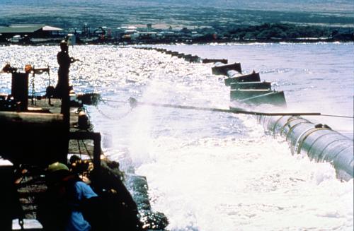
Since in principle hundreds of kilometres lined with generating
stations are conceivable, wave energy could contribute significantly to
world energy supply if an economic way of extracting this energy could
be found. The highest concentration of wave power can be found in the areas
of the strongest winds, i.e. between latitudes 40 deg. and 60 deg. in both
the northern and southern hemispheres on the eastern sides of the oceans.
Countries like the United Kingdom are thus the world's most favoured locations
for the extraction of wave power.
TECHNOLOGY
Typically ocean wave devices capture the energy of waves and convert
their energy to electricity. Wave energy devices include hydro-piezoelectric,
oscillating water columns, wave run up (tapered channel) and sea clams.
Particularly sea clams' involve wave action forcing air between blades
located on the perimeter of a circular barge structure. The air is then
run through air turbines which rotate at a shaft connected to an electrical
generator.
Europe, and in particular the United Kingdom, are looking at wave power. A recent review by the UK government has shown that there are now types of wave power devices which can produce electricity at a cost of under USD 0,10/kWh, the point at which production of electricity becomes economically viable. The most efficient of the devices, the Salter Duck can produce electricity for less than USD 0,05/kWh. The Salter Duck was developed in the 1970s by Professor Stephen Salter at the University of Edinburgh in Scotland and generates electricity by bobbing up and down with the waves. Although it can produce energy extremely efficiently it was effectively killed off in the mid 1980s when a European Union report miscalculated the cost of the electricity it produced by a factor of 10. In the last few years, the error has been realised, and interest in the Duck is becoming intense.
The Clam is another device which, Like the Salter Duck can make energy from sea swell. The Clam is an arrangement of six airbags mounted around a hollow circular spine. As waves impact on the structure air is forced between the six bags via the hollow spine which is equipped with self-rectifying turbines. Even allowing for cabling to shore, it is calculated that the Clam can produce energy for around USD 0,06 /kWh.
Both the Duck and the Clam generate energy from waves at sea. This
is useful for generating energy for offshore structures and low-lying islands.
However, where islands offer suitable sites, cliff-mounted oscillating
water column (OWC) generators have a number of advantages, not the least
of which is the fact that generators and all cabling are shore-based, making
maintenance of the former and replacement of the latter much simpler. The
OWC works on a simple principle. As a wave pours into the main chamber,
air is forced up a funnel which houses a turbine. As the wave retreats,
air is sucked down into the main chamber again, spinning the turbine in
the opposite direction
.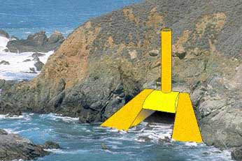
OWC machines have already been tested at a number of sites, including
Japan and Norway. The UK is on the verge of deploying Osprey II, a second
generation OWC. There is particular interest in OWC systems because of
the large amount (7,000 MW) of shoreline wave energy available for exploitation.
Costs for OWC machine-generated electricity is likely to start at USD 0,10
/kWh. The first-generation system, based on the island of Islay takes advantage
of a natural rock gully to drive a 180 kW turbine attached to an electricity
generator. Built by researchers from the Queen's University of Belfast
the system supplies electricity to the local grid, which is connected to
the mainland national grid by submarine cable However, both OWC-systems
and ocean-wave systems suffer from trying to harness violent forces. The
first Norwegian OWC was ripped off a cliff-face during a storm, the Islay
station is completely submerged under storm conditions.
![]()
PELAMIS
There have been several proposals to harness ocean waves to generate
electricity or to make other useful products such as fresh water or hydrogen.
To date none of these has been successfully commercialised. Ocean Power
Delivery Ltd. is developing a novel offshore wave energy converter called
Pelamis. The company has successfully bid for a contract to install a pair
of 375kW prototype devices off Islay, Scotland, under the 1999 Scottish
Renewables Obligation. The device has an annual capacity factor of 38%
at the site chosen. It is approximately 130metres long and 3,5metres in
diameter. It is scheduled to be installed early in 2002 and will generate
over 2,5 million kWh's of electricity per year, enough to provide power
for 150-200 homes.
The Pelamis device is a semi-submerged, articulated structure composed
of cylindrical sections linked by hinged joints. The wave induced motion
of these joints is resisted by hydraulic rams which pump high pressure
oil through hydraulic motors via smoothing accumulators. The hydraulic
motors drive electrical generators to produce electricity. Power from all
the joints is fed down a single cable to a junction on the sea bed. Several
devices can be connected together and linked to shore through a single
seabed cable. A novel joint configuration is used to induce a tuneable,
cross-coupled resonant response which greatly increases power capture in
small seas. Control of the restraint applied to the joints allows this
resonant response to be turned-up' in small seas where capture efficiency
must be maximised or turned-down' to limit loads and motions in survival
conditions.
The complete device is flexibly moored so as to swing head-on to
the incoming waves and derives its reference' from spanning successive
wave crests.
The Pelamis device has a number of important advantages over other
existing or proposed Wave Energy Converters, these include:
![]() Tuneable response
allows power capture to be maximised in small seas while limiting loads
and motions in extreme conditions
Tuneable response
allows power capture to be maximised in small seas while limiting loads
and motions in extreme conditions
![]() The head on
aspect to severe waves presents the minimum resistance to the high velocities
in extreme wave crests
The head on
aspect to severe waves presents the minimum resistance to the high velocities
in extreme wave crests
![]() The finite
length of the device is optimised to extract power from shorter wavelengths
and is unable to reference against the long waves associated with storm
conditions
The finite
length of the device is optimised to extract power from shorter wavelengths
and is unable to reference against the long waves associated with storm
conditions
![]() The small diameter
leads to local submergence or emergence in large waves limiting the forces
and moments in the structure
The small diameter
leads to local submergence or emergence in large waves limiting the forces
and moments in the structure
![]() The flexible
mooring system has a range of motion able to accommodate the largest waves
The flexible
mooring system has a range of motion able to accommodate the largest waves
THE MIGHTY WHALE
The Marine Science & Technology Centre of Japan launched the
world's largest offshore floating wave power device in July 1998, and the
full-scale prototype will be tested until the year 2000.
This floating device, called the Mighty Whale, converts wave energy
to electricity. The device measures 50 metres long by 30 metres wide, and
uses waves in the Pacific Ocean to drive three air turbines (one with a
rated output of 50 kW + 10 kW and two of 30 kW) on board the platform,
to generate 120 kW of electricity.
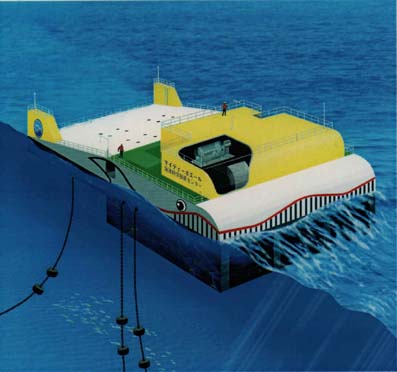
After being towed to its mooring about 1.5 km from the mouth of
Gokasho Bay, the Mighty Whale was anchored to the bottom of the sea (about
40 m deep) with six mooring lines; four lines on the seaward side and two
on the lee side. Mooring lines are designed to withstand typhoon winds,
and the unit is designed to handle waves of 8 m. The Mighty Whale converts
wave energy to electricity by using oscillating columns of water to drive
air turbines. Waves flowing in and out of the air chambers at the mouth'
of the Mighty Whale make the water level in the chambers rise and
fall. The water forces air into and out of the chambers through nozzles
on the tops of the chambers. The resulting high-speed air-flows rotate
air turbines which drive the generators. The Mighty Whale can be remotely
controlled from on-shore. In the demonstration prototype, the energy produced
is mostly used by the instruments carried on board; any surplus is used
to charge a storage battery or, when this is fully charged, is used by
a loading resistor. A safety valve protects the air turbines from stormy
weather by shutting off the flow of air if the rotation speed of the turbines
exceeds a predetermined level. So that it can be used in the future to
improve water quality, the prototype is also equipped with an air compressor
to provide aeration.
Because it has absorbed and converted most of the energy in the
wave, the Mighty Whale also creates calm sea space behind it, and this
feature can be utilised; for example, to make areas suitable for fish farming
and water sports. The structure of the Mighty Whale itself can be used
as a weather monitoring station, a temporary mooring for small vessels
or a recreational fishing platform.
![]()
SUMMARY
At the present time both tide and wave energy are suffering from
orientation problems, in the sense that neither method is strictly economical
on a large scale in comparison with conventional power sources. In addition,
neither will produce electricity at a steady rate and thus not necessarily
at times of peak demand. Wave power stations suffer even more from these
problems, their rate of production being unreliable. In Norway development
of wave power was taken a step further, concentrating on small applications
on remote islands and the like, and for quite a while a small power plant
(500 kW) operated successfully in Toftestallen until it was swept away
by the sea.
The disadvantages of wave power stations compared to maybe their closest rival - wind power - are obvious: A wave power unit will probably not have much more than three times the output of a single wind turbine, but the construction costs are likely to be far higher due to mooring problems, the bulkiness and comparative complexity of the whole structure and the water-based location. It will take some time - and far more investment into renewable energy sources - before the only comparative bonus, the fact that they use up and deface less land, will prevail over economic considerations.
And while wave energy is used successfully in very small scale applications, such as powering lighthouses or navigation buoys, its short term prospects as a major contributor to large scale energy production seems to be economically almost ruled out. So until the cost of maintaining the present rate of carbon dioxide emission is taken into account when building new power stations and a policy is adopted that depends less rigorously on market forces, the likelihood of tidal or wave power playing a major part in the energy supply of western industrialised nations even in the medium term future is small.