|
|
BIOMASS |
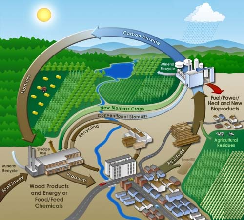
 Biomass
as the solar energy stored in chemical form in plant and animal
materials is
among the most precious and versatile resources on earth. It provides
not only
food but also energy, building materials, paper, fabrics, medicines and
chemicals. Biomass has been used for energy purposes ever since man
discovered
fire. Today, biomass fuels can be utilised for tasks ranging from
heating the
house, producing electicity or fuelling a car.iomass as
the solar energy stored in chemical form in plant and animal materials
is among
the most precious and versatile resources on earth. It provides not
only food
but also energy, building materials, paper, fabrics, medicines and
chemicals.
Biomass has been used for energy purposes ever since man discovered
fire. Today,
biomass fuels can be utilised for tasks ranging from heating the house
to
fuelling a car and running a computer.
Biomass
as the solar energy stored in chemical form in plant and animal
materials is
among the most precious and versatile resources on earth. It provides
not only
food but also energy, building materials, paper, fabrics, medicines and
chemicals. Biomass has been used for energy purposes ever since man
discovered
fire. Today, biomass fuels can be utilised for tasks ranging from
heating the
house, producing electicity or fuelling a car.iomass as
the solar energy stored in chemical form in plant and animal materials
is among
the most precious and versatile resources on earth. It provides not
only food
but also energy, building materials, paper, fabrics, medicines and
chemicals.
Biomass has been used for energy purposes ever since man discovered
fire. Today,
biomass fuels can be utilised for tasks ranging from heating the house
to
fuelling a car and running a computer.

THE CHEMICAL COMPOSITION OF BIOMASS
 |
The chemical composition of biomass varies among species, but plants consists of about 25% lignin and 75% carbohydrates or sugars . The carbohydrate fraction consists of many sugar molecules linked together in long chains or polymers. Two larger carbohydrate categories that have significant value are cellulose and hemicellulose. The lignin fraction consists of non-sugar type molecules. Nature uses the long cellulose polymers to build the fibers that give a plant its strength. The lignin fraction acts like a “glue” that holds the cellulose fibers together. |

In addition to the
aesthetic value of the planet’s flora, biomass represents a useful and
valuable
resource to man. For millennia humans have exploited the solar energy
stored in
the chemical bonds by burning biomass as fuel and eating plants for the
nutritional energy of their sugar and starch content. More recently, in
the
last few hundred years, humans have exploited fossilized biomass in the
form of
coal. This fossil fuel is the result of very slow chemical
transformations that
convert the sugar polymer fraction into a chemical composition that
resembles
the lignin fraction. Thus, the additional chemical bonds in coal
represent a
more concentrated source of energy as fuel. All of the fossil fuels we
consume
- coal, oil and natural gas - are simply ancient biomass. Over millions
of
years, the earth has buried ages-old plant material and converted it
into these
valuable fuels. But while fossil fuels contain the same constituents -
hydrogen
and carbon - as those found in fresh biomass, they are not considered
renewable
because they take such a long time to create. Environmental impacts pose another significant
distinction between biomass
and fossil fuels. When a plant decays, it releases most of its chemical
matter
back into the atmosphere. In contrast, fossil fuels are locked away
deep in the
ground and do not affect the earth’s atmosphere unless they are burned.
Wood may be the
best-known example of biomass. When burned, the wood releases the
energy the
tree captured from the sun’s rays. But wood is just one example of
biomass.
Various biomass resources such as agricultural residues (e.g. bagasse
from
sugarcane, corn fiber, straw and even nutshells), wood waste (e.g.
sawdust,
timber slash, and mill scrap), the paper trash and urban yard clippings
in
municipal waste, energy crops (fast growing trees like poplars,
willows, and
grasses like switchgrass or elephant grass), and the methane captured
from
landfills, municipal waste water treatment, and manure from cattle or
poultry,
can also be used.
Biomass is considered to
be one of the key renewable resources of the future at both small- and
large-scale levels. It already supplies 14 % of the world’s primary
energy
consumption. But for three quarters of the world’s population living in
developing countries biomass is the most important source of energy.
With
increases in population and per capita demand, and depletion of
fossil-fuel
resources, the demand for biomass is expected to increase rapidly in
developing
countries. On average, biomass produces 38 % of the primary energy in
developing countries (90 % in some countries). Biomass is likely to
remain an
important global source in developing countries well into the next
century.
Utilisation of biomass as the energy source in the world.

Even in developed
countries, biomass is being increasingly used. A number of developed
countries
use this source quite substantially, e.g. in Sweden and Austria 15 % of
their
primary energy consumption is covered by biomass. Sweden has plans to
increase
further use of biomass as it phases down nuclear and fossil-fuel
plants.
 |
In the USA , which derives 4 % of its total energy from biomass (nearly as much as it derives from nuclear power), now more than 9000 MW electrical power is installed in facilities firing biomass. But biomass could easily supply more than 20 % of US energy consumption. In other words, due to the available land and agricultural infrastructure this country has, biomass could, sustainably, replace all of the power nuclear plants generate without a major impact on food prices. Furthermore, biomass used to produce ethanol could reduce also oil imports up to 50%. |

BIOMASS
-
SOME BASIC DATA ![]()
![]() Total world biomass content - 1880 billion tonnes
Total world biomass content - 1880 billion tonnes
![]() Total
mass in tropical forests -1030 billion tonnes
Total
mass in tropical forests -1030 billion tonnes
![]() Total
mass in temperate
forests, savanna and tundra - 790 billion tonnes
Total
mass in temperate
forests, savanna and tundra - 790 billion tonnes
![]() Total
marine biomass content - 4 billion tonnes
Total
marine biomass content - 4 billion tonnes
![]() Per capita terrestrial biomass - 310 tonnes
Per capita terrestrial biomass - 310 tonnes
![]() Energy
stored in terrestrial biomass - 25 000 EJ
Energy
stored in terrestrial biomass - 25 000 EJ
![]() Net
annual
production of of
terrestrial biomass - 400 billion tonnes
Net
annual
production of of
terrestrial biomass - 400 billion tonnes
![]() Rate of
energy
storage by land biomass - 3000 EJ/y (95 TW)
Rate of
energy
storage by land biomass - 3000 EJ/y (95 TW)
![]() Total
consumption
of all forms of energy - 400 EJ/y (12 TW)
Total
consumption
of all forms of energy - 400 EJ/y (12 TW)
![]() Biomass
energy
consumption - 55 EJ/y ( 1. 7 TW)
Biomass
energy
consumption - 55 EJ/y ( 1. 7 TW)

often used against
biomass, particularly against large-scale fuel production, is that it
could
divert agricultural production away from food crops, especially in
developing
countries. The basic argument is that energy-crop programmes compete
with food
crops in a number of ways (agricultural, rural investment,
infrastructure,
water, fertilizers, skilled labour etc.) and thus cause food shortages
and
price increases. However, this so-called “food versus fuel” controversy
appears
to have been exaggerated in many cases. The subject is far more complex
than
has generally been presented since agricultural and export policy and
the
politics of food availability are factors of far greater importance.
The argument
should be analysed against the background of the world’s (or an
individual
country’s or region’s) real food situation of food supply and demand
(ever-increasing food surpluses in most industrialized and a number of
developing countries), the use of food as animal feed, the
under-utilized
agricultural production potential, the increased potential for
agricultural
productivity, and the advantages and disadvantages of producing
biofuels.
![]()
LAND AVAILABILITY
Biomass differs
fundamentally from other forms of fuels since it requires land to grow
on and
is therefore subject to the range of independent factors which govern
how, and
by whom, that land should be used. There are basically two main
approaches to
deciding on land use for biomass. The “technocratic” approach starts
from a
need for, then identifies a biological source, the site to grow it, and
then
considers the possible environmental impacts. This approach generally
had
ignored many of the local and more remote side-effects of biomass
plantations
and also ignored the expertise of the local farmers who know the local
conditions. This has resulted in many biomass project failures in the
past. The
“multi-uses” approach asks how land can best be used for sustainable
development, and considers what mixture of land use and cropping
patterns will
make optimum use of a particular plot of land to meet multiple
objectives of
food, fuel, fodder, societal needs etc. This requires a full
understanding of
the complexity of land use.
Generally
it can be said that biomass productivity can be improved since in
many place of the world is low, being much less than 5 t/ha/yr. for
woody
species without good management. Increased productivity is the key to
both
providing competitive costs and better utilisation of available land.
Advances
have included the identification of fast-growing species, breeding
successes
and multiple species opportunities, new physiological knowledge of
plant growth
processes, and manipulation of plants through biotechnology
applications, which
could raise productivity 5 to 10 times over natural growth rates in
plants or
trees.
It is now possible with good management, research, and planting
of selected
species and clones on appropriate soils to obtain 10 to 15 t/ha/yr. in
temperate areas and 15 to 25 t/ha/yr. in tropical countries. Record
yields of
40 t/ha/yr. (dry weight) have been obtained with eucalyptus in Brazil
and
Ethiopia. High yields are also feasible with herbaceous (non-woody)
crops where
the agro-ecological conditions are suitable. For example, in Brazil,
the
average yield of sugarcane has risen from 47 to 65 t/ha (harvested
weight) over
the last 15 years while over 100t/ha/yr are common in a number of areas
such as
Hawaii, South Africa, and Queensland in Australia. It should be
possible with
various types of biomass production to emulate the three-fold increase
in grain
yields which have been achieved over the past 45 years although this
would
require the same high levels of inputs and infrastructure development.
However,
in trials in Hawaii, yields of 25 t/ha/yr. have been achieved without
nitrogen
fertilizers when eucalyptus is interplanted with nitrogen fixing
Albizia trees.
ENERGY VALUE
Biomass (when considering
its energy potential) refers to all forms of plant-derived material
that can be
used for energy: wood, herbaceous plants, crop and forest residues,
animal
wastes etc. Because biomass is a solid fuel it can be compared to coal.
On a
dry-weight basis, heating values range from 17,5 GJ per tonne for
various
herbaceous crops like wheat straw, sugarcane bagasse to about 20
GJ/tonne for
wood. The corresponding values for bituminous coals and lignite are 30
GJ/tonne
and 20 GJ/tonne respectively (see tables bellow). At the time of its
harvest
biomass contains considerable amount of moisture, ranging from 8 to 20
% for
wheat straw, to 30 to 60 % for woods, to 75 to 90 % for animal manure,
and to
95 % for water hyacinth. In contrast the moisture content of the most
bituminous coals ranges from 2 to 12 %. Thus the energy density for the
biomass
at the point of production are lower than those for coal. On the other
side
chemical attributes make it superior in many ways. The ash content of
biomass
is much lower than for coals, and the ash is generally free of the
toxic metals
and other contaminants and can be used as soil fertiliser.
Energy contents comparison table.
|
|
|
|
|
|
|
|
|
|
|
|
|
|
|
|
|
|
|
|
|
|
|
|
|
|
|
|
|
|
|
|
|
|
|
|
|
|
|
|
|
|
|
|
|
|
|
|
|
|
|
|
|
|
|
|
|
|
|
|
|
|
|
|
|
|
|
|
|
|
|
|
|
|
BENEFITS OF BIOMASS AS
ENERGY SOURCE
Rural economic
development in both developed and developing countries is one of the
major
benefits of biomass. Increase in farm income and market
diversification,
reduction of agricultural commodity surpluses and derived support
payments,
enhancement of international competitiveness, revitalization of
retarded rural
economies, reduction of negative environmental impacts are most
important issues
related to utilisation of biomass as energy source. The new incomes for
farmers
and rural population improve the material welfare of rural communities
and this
might result in a further activation of the local economy. In the end,
this
will mean a reduction in the emigration rates to urban environments,
which is
very important in many areas of the world.
The number of jobs
created (for production, harvesting and use) and the industrial growth
(from
developing conversion facilities for fuel, industrial feedstocks, and
power)
would be enormous. For instance, the U.S. Department of Agriculture
estimates
that 17,000 jobs are created per every million of gallons of ethanol
produced,
and the Electric Power Research Institute has estimated that producing
5 quadrillion
Btu’s (British Thermal Units) of electricity on 50 million acres of
land would
increase overall farm income by $12 billion annually (the U.S. consumes
about
90 quadrillion Btu’s annually). By providing farmers with stable
income,
these new markets diversify and strengthen the local economy by keeping
income
recycling through the community.
Improvement in
agricultural resource utilisation has been frequently proposed in EU.
The
development of alternative markets for agricultural products might
result in
more productive uses of the cropland, currently under-utilised in many
EU
countries. In 2001, the EU
planted 128 million ha of land to crops. Approximately 0,8 million ha
were
removed from production under the set aside program. A much greater
amount is
planned to remain idled in future. It is clear that reorientation of
some of
these lands to non-food utilisation (like biomass for energy) might
avoid
misallocation of agricultural resources. European agriculture relies on
the
production of a limited number of crops, mainly used for human and
livestock
food, many of which are at present on surplus production. Reduced
prices
have resulted in low and variable income for many EU farmers. The
cultivation
of energy crops could reduce surpluses. New energy crops may be more
economically competitive than crops in surplus production.
ENVIRONMENTAL BENEFITS
The use of biomass
energy has many unique qualities that provide environmental benefits.
It can
help mitigate climate change, reduce acid rain, soil erosion, water
pollution
and pressure on landfills, provide wildlife habitat, and help maintain
forest
health through better management.
CLIMATE CHANGE
Climate change is a
growing concern world-wide. Human activity, primarily through the
combustion of fossil fuels, has released hundreds of millions of tons
of
so-called ‘greenhouse gases’ (GHGs) into the atmosphere. GHGs include
such
gases as carbon dioxide (CO2) and methane (CH4). The concern is
that all
of the greenhouse gases in the atmosphere will change the Earth’s
climate,
disrupting the entire biosphere which currently supports life as we
know
it. Biomass energy technologies can help minimize this
concern.
Although both methane and carbon dioxide pose significant threats, CH4
is 20
times more potent (though shorter-lived in the atmosphere) than CO2.
Capturing
methane from landfills, wastewater treatment, and manure lagoons
prevents the
methane from being vented to the atmosphere and allows the energy to be
used to
generate electricity or power motor vehicles. All crops,
including
biomass energy crops, sequester carbon in the plant and roots while
they grow,
providing a carbon sink. In other words, the carbon dioxide released
while
burning biomass is absorbed by the next crop growing. This is called a
closed
carbon cycle. In fact, the amount of carbon sequestered may be
greater
than that released by combustion because most energy crops are
perennials, they
are harvested by cutting rather than uprooting. Thus the roots
remain to
stabilize the soil, sequester carbon and to regenerate the following
year.
ACID RAIN
Acid rain is caused
primarily by the release of sulphur and nitrogen oxides from the
combustion of
fuels like coal. Acid rain has been implicated in the killing of
lakes,
as well as impacting humans and wildlife in other ways. Since
biomass has
practically no sulphur content, and easily mixes with coal, “co-firing”
is a
very simple way of reducing sulphur emissions and thus, reduce acid
rain.
“Co-firing” refers to burning biomass jointly with coal in a
traditionally
coal-fired power plant or heating plant.
SOIL EROSION & WATER
POLLUTION
Biomass crops can reduce
water pollution in a number of ways. Energy crops can be grown on more
marginal
lands, in floodplains, and in between annual crops areas. In all these
cases,
the crops stabilize the soil, thus reducing soil erosion. They also
reduce
nutrient run-off, which protects aquatic ecosystems. Their shade can
even
enhance the habitat for numerous aquatic organisms like fish.
Furthermore,
because energy crops tend to be perennials, they do not have to be
planted
every year. Since farm machinery spends less time going over the field,
less
soil compaction and soil disruption takes place. Another way
biomass
energy can reduce water pollution is by capturing the methane, through
anaerobic digestion, from manure lagoons on cattle, hog and poultry
farms. These enormous lagoons have been responsible for polluting
rivers and
streams across the country. By utilizing anaerobic digesters, the
farmers can
reduce odour, capture the methane for energy, and create either liquid
or
semi-solid soil fertilisers which can be used on-site or sold.
![]()
BIOMASS
FUELS
Plants are the most
common source of biomass. They have been used in the form of wood, peat
and
straw for thousands of years. Today the western world is far less
reliant on
this energy fuel. This is because of the general acceptance that coal,
oil,
natural gas and electricity are cleaner, more efficient and more in
keeping
with modernisation and technology. However this is not really the right
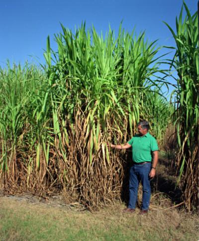
impression. Plants can either be specially grown for energy production,
or they
can be harvested from the natural environment. Plantations tend to use
breeds
of plant that are to produce a lot of biomass quickly in a sustainable
fashion.
These could be trees (e.g. willows or Eucalyptus) or other high growth
rate
plants (such as sugar cane or maize or soybean).
WOOD RESIDUES
Wood can be, and usually
is, removed sustainably from existing forests world-wide by using
methods such
as coppicing. It is difficult to estimate the mean annual
increment
(growth) of the world’s forests. One rough estimate is 12,5 billion
m3/yr. with
an content of 182 EJ equivalent to 1,3 times the total world coal
consumption.
The estimated global average annual wood harvests is around 3,4 billion
m3/yr.
(equivalent to 40 EJ/yr.), so some of the unused increment could be
recovered
for energy purposes while maintaining or possibly even enhancing the
productivity of forests.
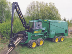 |
Operations
such as
thinning of plantations and trimming of felled trees generate large
volumes of
forestry residues. At present these are often left to rot on site -
even in
countries with fuelwood shortages. They can be collected, dried and
used as
fuel by nearby rural industry and domestic consumers, but their bulk
and high
water content makes transporting them for wider use uneconomic. In
developing
countries where charcoal is an important fuel, on-site kilns can reduce
transport costs. Mechanical harvesters and chippers have been developed
in Europe
and North America over the last 15 years to produce uniform 30-40 mm
wood chips
which can be handled, dried and burned easily in chip-fired boilers.
|
The use of forest
residues to produce hot water or steam for heating and/or power
generation is
now a growing business in many countries. American electricity
utilities have
more than 9 000 MW (output of 9 nuclear power plants) of biomass-fired
generating plant on line, much of it constructed in the last ten years.
Austria
has about 1250 MW of wood-fired heating capacity in the form of
domestic stoves
and district heating plant, burning waste wood, bark and wood chips.
Most of
these district heating systems are of 1-2 MW capacity, with a few
larger units
(around 15 MW) and a number of small-scale CHP systems.
Timber processing is a
further source of wood residues. Dry sawdust and waste produced during
the
processing of cut timber make very good fuel. The British furniture
industry is
estimated to use 35 000 tonnes of such residues a year, one third of
its production,
providing 0,5 PJ of space and water heating and process heat. In
Sweden, where
biomass already provides nearly 15% of primary energy, forestry
residues and
wood industries contribute over 200 PJ/yr., mainly as fuel for CHP
plant.
AGRICULTURAL RESIDUES
Agricultural waste is a
potentially huge source of biomass. Crop and animal wastes provide
significant
amounts of energy coming second only to wood as the dominant biomass
fuel
world-wide. Waste from agriculture includes: the portions of crop
plants discarded
like straw, whether damaged or surplus supplies, and animal dung. It
was estimated,
for example, that 110 million tonnes of dung and crop residues is used as fuel in India, compared with 133 Mt of
wood, and in China the mass of available agricultural residues has been
estimated at 2,2 times the mass of wood fuel.
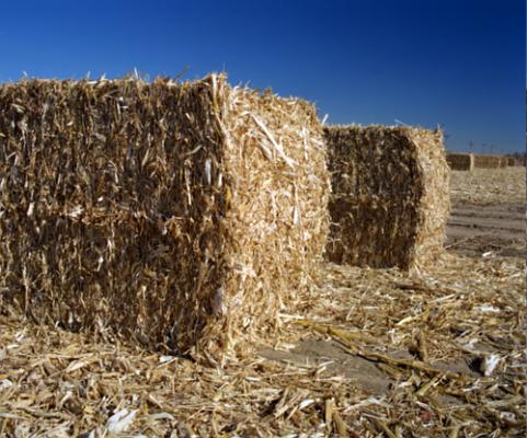
Every year, millions tonnes of straw are produced world-wide with
usually half
of it surplus to need. In many countries this is still being burned in
the
field or ploughed back into the soil, but in some developed countries
environmental legislation which restrict field burning has drawn
attention to
its potential as an energy resource Effort to remove crop residues from
soils and to use them for energy purposes
leads to a central question: how much residue should be left and
recycled
into soil to sustain production of biomass ? According to the
experience from
developed countries around 35% of crop residues can be removed from
soil
without adverse effects on future plant production.
Industrial waste that contains biomass may be used to produce energy.
For
example the sludge left after alcohol production (known as vinasse) can
produce
flammable gas. Other useful waste products include, waste from food
processing
and fluff from the cotton and textiles industry.
SHORT ROTATION PLANTS
 Biomass
can be also be
produced by so-called short-rotation plantation of trees and other
plants like
grasses (sorghum, sugarcane, switchgrass). All these plants can be used
as
fuels like wood with the main advantage of their short span between
plantation
and harvesting – typically between three and eight years. For some
grasses
harvesting is taking place every six to 12 months. Recently there are
about 100
million hectares of land utilised for tree plantation world-wide. Most
of these
trees are used for forest products markets.
Biomass
can be also be
produced by so-called short-rotation plantation of trees and other
plants like
grasses (sorghum, sugarcane, switchgrass). All these plants can be used
as
fuels like wood with the main advantage of their short span between
plantation
and harvesting – typically between three and eight years. For some
grasses
harvesting is taking place every six to 12 months. Recently there are
about 100
million hectares of land utilised for tree plantation world-wide. Most
of these
trees are used for forest products markets.
Parameters which are important in evaluating species for short
rotation
plants include availability of planting stock, ease of propagation,
survival
ability under adverse conditions and the yield potential measured as
dry matter
production per hectare per year (t/ha/y). Yield is a measure of a
plant’s
ability to utilize the site resources. It is the most important factor
when
considering biomass production due to the need to optimize/maximize
yield from
a given area of land within a given time frame at the least possible
cost. High
yielding species are therefore preferred for biomass energy systems.
Some plant communities have shown superiority in dry matter
production
compared to others grown under similar conditions. Although reported
dry matter
production of different tree species varies over a wide range depending
on soil
types and climate, certain species stand out. For Eucalyptus species,
yields of
up to 65 t/ha/y have been reported, compared to 30 and 43 t/ha/y in
Salix and
Populus species respectively.
Despite the fact that biomass plantation can be of great importance
for most
developed countries experience has shown it is unlikely to be
established on a
large scale in many developing countries, especially in poor rural
areas, so
long as biofuels (particularly wood) can be obtained at zero or near
zero cost.
BIOMASS FUELS IN DEVELOPING
COUNTRIES
Despite its wide use in
developing countries, biomass energy is usually used so inefficiently
that only
a small percentage of its useful energy is obtained. The overall
efficiency in
traditional use is only about 5-15 per cent, and biomass is often less
convenient
to use compared with fossil fuels. It can also be a health hazard in
some
circumstances, for example, cooking stoves can release particulates,
CO, NOx
formaldehyde, and other organic compounds in poorly ventilated homes,
often far
exceeding recommended WHO (World health Organisation) levels.
Furthermore, the
traditional uses of biomass, i.e., burning of wood is often associated
with the
increasing scarcity of hand-gathered wood, nutrient depletion, and the
problems
of deforestation and desertification. Recently almost 1,3 billion
people is
meeting their fuelwood needs by depleting wood reserves.
Share of
biomass on
total energy consumption:
Nepal 95 %
Malawi 94 %
Kenya 75 %
India 50 %
China 33 %
Brazil 25 %
Egypt 20 %
There is an enormous
biomass potential that can be tapped by improving the utilization of
existing
resources and by increasing plant productivity. Bioenergy can be
modernized
through the application of advanced technology to convert raw biomass
into
modern, easy-to-use carriers (such as electricity, liquid or gaseous
fuels, or
processed solid fuels). Therefore, much more useful energy could be
extracted
from biomass than at present. This could bring very significant social
and
economic benefits to both rural and urban areas. The present lack of
access to
convenient sources limits the quality of life of millions of people
throughout
the world, particularly in rural areas of developing countries. Growing
biomass
is a rural, labour-intensive activity, and can, therefore, create jobs
in rural
areas and help stem rural-to-urban migration, whilst, at the same time,
providing convenient carriers to help promote other rural industries.
Fuelwood
The term fuelwood
describe all types of fuels derived from forestry and plantation.
Fuelwood
accounts for about 10 per cent of the total used in the world. It
provides
about 20 % of all used in Asia and Latin America, and about 50 % of
total used
in Africa. However, it is the major source of, in particular for
domestic
purposes, in poor developing countries: in 22 countries, fuelwood
accounted for
25 to 49 %, in 17 countries, 50-74 %, and in 26 countries, 75-100 % of
their
respective national consumption.
More than half of the total wood harvested in the world is used as
fuelwood.
For specific countries, for example in Tanzania, the contribution can
be as
high as 97% . Although fuelwood is the major source of for most rural
and
low-income people in the developing world, the potential supply of
fuelwood is
dwindling rapidly, leading to scarcity of and environmental
degradation. It is
estimated that, for more than a third of the world population, the real
crisis
is the daily scramble to obtain fuelwood to meet domestic use.
Several studies on fuelwood supply in developing countries have
concluded
that fuelwood scarcities are real and will continue to exist, unless
appropriate approaches to resource management are undertaken. The
increase of
fuelwood production through efficient techniques, can, therefore, be
considered
as one of the major pre-requisites for attaining sustainable
development in
developing countries.
Charcoal
The main expansion in the use of charcoal in Europe came with the
industrial
revolution in England in the 17th and 18th centuries. In Sweden,
charcoal
consumption for iron making grew through most of the 19th century, and
was the
basis of the good quality tradition of Swedish steel. Today charcoal is
an
important household fuel and to a lesser extent, industrial fuel in
many
developing countries. It is mainly used in the urban areas where its
ease of
storage, high content (30 MJ/kg as compared with 15 MJ/kg in fuelwood),
lower
levels of smoke emissions, and, resistance to insect attacks make it
more
attractive than fuelwood. In the United Republic of Tanzania, charcoal
accounts
for an estimated 90 per cent of biofuels consumed in urban centres.
![]()
RESIDUES
Agricultural residues
have an enormous potential for production. In favorable circumstances,
biomass
power generation could be significant given the vast quantities of
existing
forestry and agricultural residues - over 2 billion t/yr. world-wide.
This
potential is currently under-utilized in many areas of the world. In
wood-scarce areas, such as Bangladesh, China, the northern plains of
India, and
Pakistan, as much as 90 per cent of household in many villages covers
their
energy needs with agricultural residues. It has been estimated that
about 800
million people world-wide rely on agricultural residues and dung for
cooking,
although reliable figures are difficult to obtain. Contrary to the
general
belief, the use of animal manure as a source is not confined to
developing
countries alone, e.g., in California a commercial plant generates about
17.5 MW
of electricity from cattle manure, and a number of plants are operating
in the
Europe.
There is 54 EJ of biomass energy theoretically available from
recoverable
residues in developing countries and 42 EJ in industrialized regions.
The
amount of potentially recoverable residues includes the three main
sources:
forestry, crops and dung. The calculations assume only 25 per cent of
the
potentially harvestable residues are likely to be used. Sugarcane
residues
(bagasse, and leaves) - are particularly important and offer an
enormous
potential for generation of electricity. Generally, residues are still
used
very inefficiently for electricity production, in many cases
deliberately to
prevent their accumulation, but also because of lack of technical and
financial
capabilities in developing countries.
Depending on the choice of the gas turbine technology and the extent to
which
cane tops and leaves can be used, according to some estimates amount of
electricity that can be produced from cane residues could be up to 44
times the
on-site needs of the sugar factory or alcohol distillery. For each
litre of
alcohol produced a BIG/STIG technology unit could be able to produce
more than
11 kWh of electricity in excess of the distillery’s needs (about 820
kWh/t).
Another estimate of bagasse in condensing-extraction steam turbines
puts the
surplus electricity values at 20-65 kWh per ton of cane, and this
surplus could
be doubled by using barbojo for generation during the off-season. The
cost of
the generated electricity is estimated to be about $US 0,05/kWh.
Revenues from
the sale of electricity co-produced with sugar could be comparable with
sugar
revenues, or alternatively, revenues from the sale of electricity
co-produced
with ethanol could be much greater than the alcohol revenues. In the
latter
instance, electricity would become the primary product of sugarcane,
and
alcohol the by-product.
In India alone, electricity production from sugarcane residues by the
year 2030
could be up to 550 TWh/year (the total electricity production from all
sources
in 2004 was around 530 TWh . Globally, it has been estimated that about
50,000
MW could be supported by currently produced residues. The theoretical
potential
of residues in the 80 sugarcane-producing developing countries could be
up to
2800 TWh/yr. Studies of the sugarcane industry indicate a combined
power
capability in excess of 500 TWh/yr. Assuming that a third of the global
residue
resources could economically and sustainably be recovered by new energy
technology, 10 per cent of the current global electricity demand could
be
generated.
Obviously, to achieving such goals, these are theoretical calculations
with
country- and site specific problems. They do however emphasize the
potential
which many countries have to provide a substantial proportion of their
energy
needs from biomass grown on a sustainable basis.
METHODS
OF
GENERATING ENERGY FROM BIOMASS
Nearly all types of raw
biomass decompose rather quickly, so few are very good long-term energy
stores;
and because of their relatively low energy densities, they are likely
to be
rather expensive to transport over appreciable distances. Recent years
have
therefore seen considerable effort devoted to the search for the best
ways to
use these potentially valuable sources of energy.
In considering the methods for extracting the energy, it is possible
to
order them by the complexity of the processes involved:
![]() Direct
combustion of biomass.
Direct
combustion of biomass.
![]() Thermochemical
processing to upgrade the biofuel. Processes in this category include
pyrolysis, gasification and liquefaction.
Thermochemical
processing to upgrade the biofuel. Processes in this category include
pyrolysis, gasification and liquefaction.
![]() Biological
processing.
Natural processes such as anaerobic digestion and fermentation which
lead to a
useful gaseous or liquid fuel.
Biological
processing.
Natural processes such as anaerobic digestion and fermentation which
lead to a
useful gaseous or liquid fuel.
The immediate ‘product, of some of these processes is heat - normally used at place of production or at not too great a distance, for heating purposes, chemical processing or to generate steam for power production. For other processes the product is a solid, liquid or gaseous fuel: charcoal, liquid fuel like ethanol as a petrol substitute or additive, gas for sale or for power generation using either steam or gas turbines.
COMBUSTION

The technology of direct
combustion as the most obvious way of extracting energy from biomass is
well
understood, straightforward and commercially available. Combustion
systems come
in a wide range of shapes and sizes burning virtually any kind of fuel,
from
chicken manure and straw bales to tree trunks, municipal refuse and
scrap
tyres. Some of the ways in which heat from burning wastes is currently
used
include space and water heating, industrial processing and electricity
generation. One problem with this method is its low efficiency. With an
open
fire most of the heat is wasted and is not used to cook or whatever.
Combustion of wood can be divided into four phases:
![]() Water
inside the
wood boils off. Even wood that has been dried for ages has as much as
15 to 20%
of water in its cell structure.
Water
inside the
wood boils off. Even wood that has been dried for ages has as much as
15 to 20%
of water in its cell structure.
![]() Gas
content is
freed from the wood. It is vital that these gases should burn and not
just
disappear up the chimney.
Gas
content is
freed from the wood. It is vital that these gases should burn and not
just
disappear up the chimney.
![]() The gases
emitted
mix with atmospheric air and burn at a high temperature.
The gases
emitted
mix with atmospheric air and burn at a high temperature.
![]() The rest
of the
wood (mostly carbon) burns. In perfect combustion the entire energy is
utilised
and all that is left is a little pile of ashes.
The rest
of the
wood (mostly carbon) burns. In perfect combustion the entire energy is
utilised
and all that is left is a little pile of ashes.
Three things are needed for effective burning:
![]() high
enough
temperatures;
high
enough
temperatures;
![]() enough
air, and
enough
air, and
![]() enough
time for
full combustion.
enough
time for
full combustion.
If not enough air gets
in, combustion is incomplete and the smoke is black from the unburned
carbon.
It smells terrible, and you get soot deposited in the chimney, with the
risk of
fire. If too much air gets in the temperature drops and the gases
escape
unburned, taking the heat with them. The right amount of air gives the
best
utilisation of fuel. No smell, no smoke, and very little risk of
chimney fires.
Regulation of the air supply depends largely on the chimney and the
draught it
can put up.
Direct combustion is the simplest and most common method of
capturing the
energy contained within biomass. Boiling a pan of water over a wood
fire is a
simple process. Unfortunately, it is also very inefficient, as a little
elementary calculation reveals.
The energy content of a cubic metre dry wood is 10 GJ, which is ten
million
kJ. To raise the temperature of a litre of water by 1 degree Celsius
requires
4,2 kJ of heat energy. Bringing a litre to the boil should therefore
require
rather less than 400 kJ, equivalent to 40 cubic centimetres of wood -
one small
stick, perhaps. In practice, with a simple open fire we might need at
least
fifty times this amount: a conversion efficiency no better than 2%.
Designing a stove or boiler which will make rather better use of
valuable
fuel requires an understanding of the processes involved in the
combustion of a
solid fuel. The first is one which consumes rather than produces
energy: the
evaporation of any water in the fuel. With reasonably dry fuel,
however, this
uses only a few percent of the total energy. In the combustion process
itself
there are always two stages, because any solid fuel contains two
combustible
constituents. The volatile matter is released as a mixture of vapours
or
vaporised tars and oils by the fuel as its temperature rises. The
combustion of
these produces the little spurts of pyrolysis.
Modern combustion facilities (boilers) usually produce heat, steam
(used in
industrial process) or electricity. Direct combustion systems vary
considerably
in their design. The fuel choice makes a difference in the design and
efficiency of the combustion system. Direct combustion technology using
biomass
as the fuel is very similar to that used for coal. Biomass and
coal can
be handled and burned in essentially the same fashion. In fact, biomass
can be
“co-fired” with coal in small percentages in existing coal boilers. The
biomass
which is co-fired are usually low-cost feedstocks, like wood or
agricultural
waste, which also help to reduce the emissions typically associated
with coal.
Coal is simply fossilized biomass heated and compressed over millions
of years.
The process which coal undergoes as it is heated and compressed deep
within the
earth, adds elements like sulphur and mercury to the coal. Burning coal
for
heat or electricity releases these elements, which biomass does not
contain.
PYROLYSIS
Pyrolysis is the
simplest and almost certainly the oldest method of processing one fuel
in order
to produce a better one. A wide range of energy-rich fuels can be
produced by
roasting dry wood or even the straw. The process has been used for
centuries to
produce charcoal. Conventional pyrolysis involves heating the original
material
(which is often pulverised or shredded then fed into a reactor vessel)
in the
near-absence of air, typically at 300 - 500 °C, until the volatile
matter has
been driven off. The residue is then the char - more commonly known as
charcoal
- a fuel which has about twice the energy density of the original and
burns at
a much higher temperature. For many centuries, and in much of the world
still
today, charcoal is produced by pyrolysis of wood. Depending on the
moisture
content and the efficiency of the process, 4-10 tonnes of wood are
required to
produce one tonne of charcoal, and if no attempt is made to collect the
volatile matter, the charcoal is obtained at the cost of perhaps
two-thirds of
the original energy content.
Pyrolysis can also be carried out in the presence of a small
quantity of
oxygen (‘gasification’), water (‘steam gasification’) or hydrogen
(‘hydrogenation’). One of the most useful products is methane, which is
a
suitable fuel for electricity generation using high-efficiency gas
turbines.
With more sophisticated pyrolysis techniques, the volatiles can be
collected, and careful choice of the temperature at which the process
takes
place allows control of their composition. The liquid product has
potential as
fuel oil, but is contaminated with acids and must be treated before
use. Fast
pyrolysis of plant material, such as wood or nutshells, at temperatures
of
800-900 degrees Celsius leaves as little as 10% of the material as
solid char
and converts some 60% into a gas rich in hydrogen and carbon monoxide.
This
makes fast pyrolysis a competitor with conventional gasification
methods (see
bellow), but like the latter, it has yet to be developed as a treatment
for
biomass on a commercial scale.
At present, conventional pyrolysis is considered the more attractive
technology. The relatively low temperatures mean that fewer potential
pollutants are emitted than in full combustion, giving pyrolysis an
environmental advantage in dealing with certain wastes. There have been
some
trials with small-scale pyrolysis plants treating wastes from the
plastics industry
and also used tyres - a disposal problem of increasingly urgent concern.
![]()
GASIFICATION
The basic principles of
gasification have been under study and development since the early
nineteenth
century, and during the Second World War nearly a million biomass
gasifier-powered vehicles were used in Europe. Interest in biomass
gasification
was revived during the “energy crisis” of the 1970s and slumped again
with the
subsequent decline of oil prices in the 1980s. The World Bank (1989)
estimated
that only 1000 - 3000 gasifiers have been installed globally, mostly
small
charcoal gasifiers in South America.
Gasification based on wood as a fuel produces a flammable gas
mixture of
hydrogen, carbon monoxide, methane and other non flammable by products.
This is
done by partially burning and partially heating the biomass (using the
heat
from the limited burning) in the presence of charcoal (a natural
by-product of
burning biomass). The gas can be used instead of petrol and reduces the
power
output of the car by 40%. It is also possible that in the future this
fuel
could be a major source of energy for power stations.
SYNTHETIC FUELS
A gasifier which uses
oxygen rather than air can produce a gas consisting mainly of H2, CO
and CO2,
and the interesting potential of this lies in the fact that removal of
the CO2
leaves the mixture called synthesis gas, from which almost any
hydrocarbon
compound may be synthesised. Reacting the H2 and CO is one way to
produce pure
methane. Another possible product is methanol (CH3OH), a liquid
hydrocarbon
with an energy density of 23 GJ per tonne. Producing methanol in this
way involves
a series of sophisticated chemical processes with high temperatures and
pressures and expensive plant, and one might wonder why it is of
interest. The
answer lies in the product: methanol is that valuable commodity, a
liquid fuel
which is a direct substitute for gasoline. At present the production of
methanol using synthesis gas from biomass is not a commercial
proposition, but
the technology already exists, having been developed for use with coal
as
feedstock - as a precaution by coal-rich countries at times when their
oil
supplies were threatened.
FERMENTATION
Fermentation of sugar solution is the way how ethanol (ethyl alcohol) can be produced. Ethanol is a very high liquid energy fuel which can be used as the substitute for gasoline in cars. This fuel is used successfully mainly in Brazil. Suitable feedstocks include crushed sugar beet or fruit. Sugars can also be manufactured from vegetable starches and cellulose by pulping and cooking, or from cellulose by milling and treatment with hot acid. After about 30 hours of fermentation, the brew contains 6-10 per cent alcohol, which can be removed by distillation as a fuel. Fermentation is an anaerobic biological process in which sugars are converted to alcohol by the action of micro-organisms, usually yeast. The resulting alcohol is ethanol (C2H3OH) rather than methanol (CH3OH), but it too can be used in internal combustion engines, either directly in suitably modified engines or as a gasoline extender in gasohol: gasoline (petrol) containing up to 20% ethanol.
The value of any particular type of
biomass as feedstock for fermentation
depends on the ease with which it can be converted to sugars. The best
known
source of ethanol is sugar-cane - or the molasses remaining after the
cane
juice has been extracted. Other plants whose main carbohydrate is
starch
(potatoes, corn and other grains) require processing to convert the
starch to
sugar. This is commonly carried out, as in the production of some
alcoholic
drinks, by enzymes in malts. Even wood can act as feedstock, but its
carbohydrate, cellulose, is resistant to breakdown into sugars by acid
or
enzymes (even in finely divided forms such as sawdust), adding further
complication to the process. The liquid resulting from fermentation
contains only about 10% ethanol, which
must be distilled off before it can be used as fuel. The energy content
of the
final product is about 30 GJ/t, or 24 GJ/m3. The complete process
requires a
considerable amount of heat, which is usually supplied by crop residues
(e.g.
sugar cane bagasse or maize stalks and cobs). The energy loss in
fermentation
is substantial, but this may be compensated for by the convenience and
transportability of the liquid fuel, and by the comparatively low cost
and
familiarity of the technology.
ANAEROBIC DIGESTION
Nature has a provision
of destroying and disposing of wastes and dead plants and animals. Tiny
micro-organisms called bacteria carry out this decay or decomposition.
The
farmyard manure and compost is also obtained through decomposition of
organic
matter. When a heap of vegetable or animal matter and weeds etc. die or
decompose at the bottom of back water or shallow lagoons then the
bubbles can
be noticed rising to the surface of water. Some times these bubbles
burn with
flame at dusk. This phenomenon was noticed for ages, which puzzled man
for a
long time. It was only during the last 200 years or so when scientists
unlocked
this secret, as the decomposition process that takes place under the
absence of
air (oxygen). This gas, production of which was first noticed in marshy
places,
was and is still called as ‘Marsh Gas’. It is now well known that this
gas
(Marsh Gas) is a mixture of Methane (CH4) and Carbon dioxide (CO2) and
is
commonly called as the ‘Biogas’. As per records biogas was first
discovered by
Alessandro Volta in 1776 and Humphery Davy was the first to pronounce
the
presence of combustible gas Methane in the Farmyard Manure in as early
as 1800.
The technology of scientifically harnessing this gas from any
biodegradable
material (organic matter) under artificially created conditions is
known as
biogas technology.
Anaerobic digestion,
like pyrolysis, occurs in the absence of air; but in this case the
decomposition is caused by bacterial action rather than high
temperatures. It
is a process which takes place in almost any biological material, but
is
favoured by warm, wet and of course airless conditions.
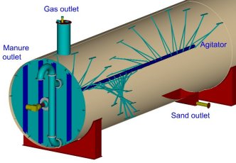
BIOGAS
Biogas
is a valuable fuel
which is in many countries produced in purpose built digesters filled
with the
feedstock like manure or sewage. Digesters range in size from one cubic
meter
for a small ‘household’ unit to more than thousand cubic meters used in
large
commercial installation or farm plants. The input may be continuous or
in
batches, and digestion is allowed to continue for a period of from ten
days to
a few weeks. The bacterial action itself generates heat, but in cold
climates
additional heat is normally required to maintain the ideal process
temperature
of at least 35 degrees Celsius, and this must be provided from the
biogas. In
extreme cases all the gas may be used for this purpose, but although
the net
energy output is then zero, the plant may still pay for itself through
the
saving in fossil fuel which would have been needed to process the
wastes. A
well-run digester can produce 200-400 m3 of biogas with a methane
content of
50% to 75% for each dry tonne of input.
 |
 |
|
|
|
 |
 |
|
|
|
LANDFILL GAS
A large proportion of
ordinary domestic refuse - municipal solid wastes - is biological
material and
its disposal in landfills creates suitable conditions for anaerobic
digestion. Landfill
sites that produce methane has been known for decades, and recognition
of the
potential hazard led to the fitting of systems for burning it off;
however, it
was only in the 1970s that serious attention was paid to the idea of
using this
‘undesirable’ product.
The waste matter is more miscellaneous in a landfill than in a biogas
digester,
and the conditions neither as warm nor as wet, so the process is much
slower,
taking place over years rather than weeks. The end product, known as
landfill
gas, is again a mixture consisting mainly of CH4 and CO2. In theory,
the
lifetime yield of a good site should lie in the range 150-300 m3 of gas
per
tonne of wastes, with between 50% and 60% by volume of methane. This
suggests a
total energy of 5-6 GJ per tonne of refuse, but in practice yields are
much
less.
In developing a site, each area is covered with a layer of impervious
clay or
similar material after it is filled, producing an environment which
encourages
anaerobic digestion. The gas is collected by an array of interconnected
perforated pipes buried at depths up to 20 metres in the refuse. In new
sites
this pipe system is constructed before the wastes start to arrive, and
in a
large well-established landfill there can be several miles of pipes,
with as
much as 1000 m3 an hour of gas being pumped out.
Increasingly, the gas from landfill sites is used for power generation.
At
present most plants are based on large internal combustion engines,
such as
standard marine engines. Driving 500 kW generators, these are well
matched to
typical gas supply rates of the order of 10 GJ an hour.
![]()
Heating
buildings with biomass
District heating system means the central biomass plant which
provides heat
to several public, commercial, and residential buildings located around
in the
area near the heating plant. These heating systems offer a many
advantages over
the use of individual heating boilers in houses. Efficiency and the
level of
automation are the most important ones. Higher efficiency in central
heating
plants leads to lower fuel consumption, labour requirements and also
emissions.
On the other hand district heating systems may have some limitation in
order to
accomodate new consumers when theete is not sufficient capacity (output
power,
piping etc).
WOOD
BOILERS
Most common process of
biomass combustion is burning of wood. In developed countries replacing
oil or
coal-fired central heating boiler with a wood burning one can save
between 20
and 60% on heating bills, because wood costs less than oil or coal. At
the same
time wood burning units are eco-friendly. They only emit the same
amount of the
greenhouse gas CO2 as the tree absorbed when it was growing. So burning
wood
does not contribute to global warming. Since wood contains less sulphur
than
oil does, less sulphate is discharged into the atmosphere. This means
less acid
rain and less acid in the environment.
SMALL BOILERS
Small wood burning
boilers are frequently used for heating houses. There are approx.
70,000 small
boilers burning firewood, wood chips, or wood pellets in Denmark alone.
Such a
boiler gives off its heat to radiators in exactly the same way as e.g.
an
oil-fired one. In this it differs from a wood burning stove, which only
gives
off its heat to the room it is in. In other words a wood burning boiler
can
heat whole house and provide hot water. For a single family home, a
hand-fired
wood burning boiler is usually the best and most economical investment.
In
larger places such as farms the saving from burning wood is often so
great that
it pays to install an automatic stoker unit burning wood pellets.
Many of small boilers are manually fired with storage tank for wood.
Distinctions should be made between manually fired boilers for fuelwood
and
automatically fired boilers for wood chips and wood pellets. Manually
fired
boilers are installed with storage tank for hot water so as to
accumulate the
heat energy from fuel. Automatic boilers are equipped with a silo
containing
wood pellets or wood chips. A screw feeder feeds the fuel
simultaneously with
the output demand of the dwelling.
Great advances have been made over the recent 10 years for both boiler
types in
respect of higher efficiency and reduced emission from the chimney
(dust and
carbon monoxide). Improvements have been achieved particularly in
respect of
the design of combustion chamber, combustion air supply, and the
automatics
controlling the process of combustion. In the field of manually fired
boilers,
an increase in the efficiency has been achieved from below 50% to
75-90%. For
the automatically fired boilers,
an increase in
the efficiency from60% to 85-92% has been achieved.
MANUALLY
FIRED BOILERS
The principal rule is
that manually fired boilers for fuelwood only have an acceptable
combustion at
the boiler rated output (at full load). At individual plants with
oxygen
control, the load can, however, be reduced to approx. 50% of the
nominal output
without thereby influencing neither the efficiency nor emissions. By
oxygen
control, a lambda probe measures the oxygen content in the flue gas,
and the
automatic boiler control varies the combustion air inlet.
The same system is used in cars. In order for the boiler not to need
feeding at
intervals of 2-4 hours a day, during the coldest periods of the year,
the
fuelwood boiler nominal output is selected so as to be up to 2-3 times
the output
demand of the dwelling. Boilers designed for fuelwood should always be
equipped
with storage tank for hot water. This ensures both the greatest comfort
for the
user and the least financial and environmental strain. In case of no
storage
tank, an increased corrosion of the boiler is often seen due to
variations in
water and flue gas temperatures.
AUTOMATICALLY FIRED BOILERS
Despite an often simple
construction, most of the automatically fired boilers can achieve an
efficiency
of 80-90% and a CO emission of approx. 100 ppm (100 ppm = 0.01 volume
%). For
some boilers, the figures are 92% and 20 ppm, respectively. An
important
condition for achieving these good results is that the boiler
efficiency during
day-to-day operation is close to full load. For automatic boilers, it
is of
great importance that the boiler nominal output (at full load) does not
exceed
the max. output demand in winter periods. In the transition periods
(3-5
months) spring and autumn, the output demand of the dwelling will
typically be
approx. 20-40% of the boiler nominal output, which means a deteriorated
operating result. During the summer period, the output demand of the
dwelling
will often be in the range of 1-3 kW, since only the hot water supply
will be
maintained. This equals 5 -10% of the boiler nominal output. This
operating
method reduces the efficiency - typically 20-30% lower than that of the
nominal
output - and an increased negative effect on the environment. The
alternative
to the deteriorated summer operating is to combine the installation
with a
storage tank and solar collectors.
MANUALLY-FIRED BOILERS
BURN-THROUGH
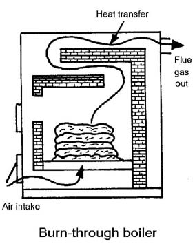 |
Nearly all old-fashioned cast iron stoves act on the burn-through principle: air comes in from below and passes upwards through the fuel. In burn-through boilers the wood burns very quickly. The gases do not burn very well, since the boiler temperature is low. Most of the gas goes up the chimney, and the energy with it. The flue gases have a very short space in which to give off their heat to the boiler in the convection section. By and large, burn-through furnaces are unsuitable for wood. The useful effect of a burn-through boiler is typically under 50%. |
UNDERBURN BOILERS
 |
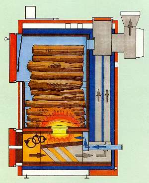
Underburn boiler is very different from a burn-through one. The air is not drawn through all the fuel at once, but only through part of it. Only the bottom layer of wood burns; the rest dries out and gives off its gases very slowly. Adding extra air (so-called “secondary air”) direct to the flames burns the gases more effectively. In modern underburning boilers the combustion chamber is ceramic lined, which insulates well and keeps the heat in. This gives a high temperature of combustion, burning the gases most effectively. An underburning boiler typically has a useful effect of 65-75%. |
 |
In reverse combustion too, air is only added to part of the fuel. As in underburning, the gases leave the fuel slowly and are burnt efficiently. Secondary air is also led into an earthenware-lined chamber, giving a high temperature of combustion. The flue gas has to pass through the entire boiler, giving it plenty of time to give up its heat. The useful effect is typically of the order of 75-85%. Some reverse combustion boilers have a blower instead of natural draught. Such boilers often have slightly better combustion, with less soot and pollution than ones with natural draught, but their useful effect is not significantly better. |
THE EFFICIENCY OF THE BOILER
How good a boiler is
partially depends on the proportion of the energy in the fuel that it
transfers
to the central heating system. This proportion is called the
“efficiency”. The
efficiency of a boiler is defined as the relationship between the
energy in the
hot water and that in the wood: the higher the efficiency, the more of
the
energy in the fuel is transferred to the water in the boiler. Good
boilers have
a efficiency of the order of 80-90%.
The a wood consumption in reverse burning boiler is typically between 4
kg/hour
for 18 kW boiler to 18 kg/hr for 80 kW boiler. In Central European
condition an
average single family house (150 m2) need cca 12 m3 of wood for the
whole
heating season. Typical boilers can burn wood logs up to 80 cm
long. For
more technical data for Central European conditions see the table
bellow.
|
|
|
|
|
|
|
|
|
|
|
|
|
|
|
|
|
|
|
|
|
|
|
|
BURNING WOOD COMBINED WITH
SOLAR
HEATING
If the building is
equipped with the wood burning unit, it is recommended also to consider
putting
in solar heating. The wood burning boiler and the solar panels can
frequently
use the same storage tank, reducing the cost of the system as a whole.
At the
same time it makes it unnecessary to have a fire going in summer just
to get
hot water. And it is cheaper to use solar energy than to burn the wood!
FUEL CHOICE
 Whatever
fuel is chosen
for use, it must be dry. Newly felled timber has a water content of
about 50%,
which makes it uneconomical to burn. This is because a proportion of
the energy
in the wood goes to evaporating the water off, giving less energy for
heat. So
wood has to be dried before it can be burnt. The best thing to do is to
leave
the wood to dry for at least a year, and preferably two. It is easiest
to stack
it in an outdoor woodshed so that the rain cannot get at it.
Whatever
fuel is chosen
for use, it must be dry. Newly felled timber has a water content of
about 50%,
which makes it uneconomical to burn. This is because a proportion of
the energy
in the wood goes to evaporating the water off, giving less energy for
heat. So
wood has to be dried before it can be burnt. The best thing to do is to
leave
the wood to dry for at least a year, and preferably two. It is easiest
to stack
it in an outdoor woodshed so that the rain cannot get at it.
Never burn wood that has been painted or glued, since toxic gases
are formed
on combustion. Nor should one burn refuse such as waxed paper milk
cartons and
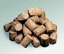
that sort of thing. You can also burn wood briquettes. They are made of
compressed sawdust and wood shavings, about 10 or 20 cm long and 5 cm
in
diameter. Because they are compressed and have a low water content they
have a
higher energy density than ordinary wood, so they need less storage
space.
CHIMNEY
Chimney is responsible
for the draught going through the boiler. The difference in the density
of the
air between the top of the chimney and the outlet on the boiler is what
creates
the draught. So the height of the chimney, the insulation, and thus the
temperature of the smoke all contribute to the draught. Bends and
horizontal
bits of piping reduce the draught. They create resistance, which the
hot air
has to overcome. So the idea is to have as few horizontal flues and
bends as
possible. Some boilers have a built-in blower, ensuring a proper
draught at all
times.
BOILER MAINTENANCE
A boiler must be
installed and maintained properly. This increases its life and the
safety. Most
countries have regulations about siting: in some places boilers have to
be put
in a separate room. The chimney will need sweeping at least once a
year. This
reduces the risk of fire. Too much soot may mean that there is not
enough air flowing
through.
WOOD PELLETS AND WOOD CHIPS IN AUTOMATICALLY-FIRED BOILERS
|
The automatic boiler is connected to the central heating system in exactly the same way as e.g. an oil-fired one. The heat of combustion is transferred to water, which is heated up and carried round the house to the radiators. The automatic boiler thus supplies heat to all the radiators in the house, unlike a wood burning stove, which only heats the room it is in. Pellets and wood-chips are of a size and shape that make them ideal for automatic boilers, since they can be fed in directly from a bunker. This makes it much easier to stoke, since the bunker only needs filling up once or twice a week. In hand-fired units like wood burning boilers, one has to stoke up several times a day - though they are usually cheaper to buy than automatic ones. |
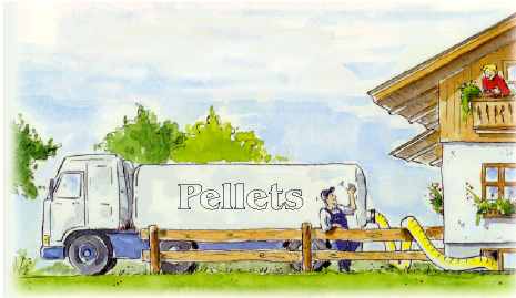
WOOD PELLETS
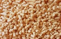 |
Wood pellets are a comparatively new and attractive form of fuel. When people burn wood pellets, they are utilising an energy resource that would otherwise have gone to waste or been dumped in a landfill. Pellets are usually made out of waste (sawdust and wood shavings), and are used in large quantities by district heating systems. The pellets are made in presses, and come out 1-3 cm long and about 1 cm wide. They are clean, pleasant smelling and smooth to touch. Wood pellets have a low moisture content (under 10% by weight), giving them a higher combustion value than other wood fuels. The fact that they are pressed means they take up less space, so they have a higher volume energy (more energy per cubic meter). The burning process is highly combustible and produces little residue. Some countries have exempted pellet appliances from the smoke emission testing requirements. |

There are different
kinds of pellets. Some manufacturers use a bonding agent to extend the
life of
the pellets; others make them without it. The bonder used often
contains
sulphur, which goes up the chimney on burning. Sulphate pollution
contributes
to acid rain and chimney corrosion, so it is best to buy pellets
without a
bonding agent.
Wood pellets characteristics:
Diameter : 5 - 8 mm
Length : max. 30 mm
Density : min. 650 kg/m3
Moisture content : max. 8% of weight
Energy value : 4,5 - 5,2 kWh/kg
2 kg pellets = 1 litre of heating oil
There are many
advantages in using pellets as the fuel of choice. No trees are cut to
make the
pellets - they are only made from leftover wood residue. Burning pellet
fuel
actually helps reduce waste created by lumber production or furniture
manufacturing. There are no additives put into the pellets to make them
burn
longer or more efficiently. Pellet fuel does not smoke or give off any
harmful
fumes. Using this fuel reduces the need for fossil fuels which are
known to be
harmful for the environment.
The cost of pellet fuel may depend on the geographic region where it is
sold,
and the current season. Whether users live in a condominium in the city
or a
home in the country, pellet fuel is among the safest, healthiest way to
heat.
This technology is also valuable for non-residential buildings such as
hotels,
resorts, restaurants, retail stores, offices, hospitals, and schools.
Pellets
are recently used in 20.000 buildings in Germany (3% of all boilers)
and in over
500 000 homes in North America.
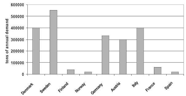
Annual pellet
consumption in selected countries in 2006.
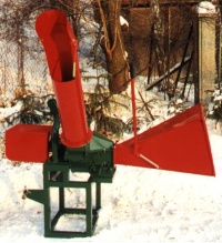
WOOD CHIPS
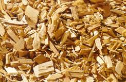 |
Wood-chips
are made of
waste wood from the forests. Trees have to be thinned to make room for
commercial timber (beams, flooring, furniture). Wood-chips are thus a
waste
product of normal forestry operations. Wood is cut up in
mechanical
chippers. The size and shape of the chips depends on the machine, but
they are
typically about a centimeter thick and 2 to 5 cm long. The water
content of
newly felled chips is usually about 50% by weight, but this drops
considerably
on drying. Careful processing and drying enable optimal storage and
trouble-free operation of heating systems
with negligible
production of ash and low emissions. |
 |
 |
|
|
|
Wood chips
are usually locally
produced and environmentally friendly energy source which are not
subject to
crises. Their utilisation also secure domestic jobs. It is mainly local
farmers
who are involved with the production and sales of wood chips. And for their production not one single tree
more has to be cut down. Every year, more wood grows in forrests than
is used thus
all kinds of waste wood material is suitable for use as wood chips
including
wood damaged by storms. In many countries like in Denmark wood-chips
currently
produced are burnt in wood-chip fired district heating stations. For
the
utilisation in single family houses they are usually delivered by road,
so
there must be facilities for storing at least 20 m3 of chips under
cover if
they are to be used in an automatic burner.
Wood logs, chips and pellets
In the table bellow you can find a comparison of different wood
burning
systems for single family house 150 m2 (12 kW heat load). Data are from
Austria.
|
Fuel |
Fuel
consumption in heating season |
Operation |
|
Logs |
12 m3 |
Fuel input 1-2 times a day |
|
Wood chips |
28 m3 |
Fuel input 1-2 times a year |
|
Wood Pellets |
7,5 m3 |
Automatic |
BOILER TYPES FOR WOOD PELLETS AND
WOOD CHIPS
Automatic furnaces come in three types :
![]() Compact
units in
which the boiler and bunker are in one.
Compact
units in
which the boiler and bunker are in one.
![]() Stoker-fired
units, with separate boiler and bunker.
Stoker-fired
units, with separate boiler and bunker.
![]() Boilers
with
built-in pre-furnace.
Boilers
with
built-in pre-furnace.
![]()
COMPACT UNITS
In compact units the
fuel is fed into the fire from the bunker by an automatic feeder. The
rate at
which fuel is fed in is determined by a thermostat, which puts less in
when the
water is hot and more in when it is cold. Compact units are excellent
for wood
pellets, but not for wood-chips. This is due to the lower volume energy
of
chips, so that stoking has to be more frequent. In addition, the water
content
of wood-chips is often so high that compact units do not combust them
properly.
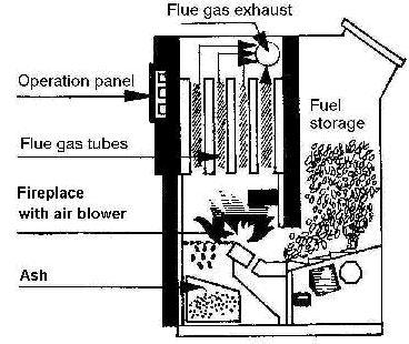
In
stoker-fired units too, the fuel is automatically fed into the boiler.
This is
a helical conveyor which conveys the fuel from the bunker to the
boiler. The
fuel is fed in at the bottom of the grate, where it burns. As in
compact units,
feed-in is thermostatically controlled. Wood pellets are best for
stoker-fired
units, but chips can also be used if the unit is designed for them. The
chips
must not be too moist, so they need drying first. The best way of doing
this is
to leave the trees outside to dry until they are put through the
chipper. Chips
can also be dried under cover after being cut up. If wood-chips are
used, they
need drying under cover for at least two months. They also need a lot
of
storage space.
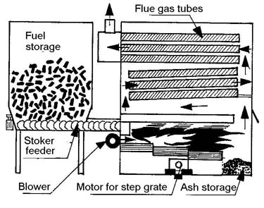
In the
third type of unit most of the combustion takes place at high
temperature in a
pre-furnace. The pre-furnace is earthenware-lined, allowing high
temperatures
to be maintained. A pre-furnace-mounted boiler is therefore highly
suitable for
burning wet wood-chips. Heat comes in from the pre-furnace and is
transferred
to the water in the boiler. Any gases not combusted in the pre-furnace
are
burnt off in the boiler. Boilers fitted with pre-furnace are designed
for
burning wood-chips. Some can also burn pellets, though others would be
damaged
by the heat generated by the dry fuel. Ask the manufacturer before
buying.
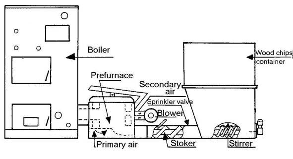
MAINTENANCE
Maintenance is very
important, otherwise there is a risk of chimney fires and carbon
monoxide
poisoning. A properly maintained fire utilises fuel better and gives
better
value for money. The working life of the unit also depends on
maintenance.
Straw has a heating
value which is similar to that of wood and can be used as a fuel in
boilers.
Nevertheless there are some difficulties which make straw a fuel source
utilised only in large boilers usually connected to district heating
systems
and agriculture sector.
Straw is a difficult type of fuel. It is difficult to handle and to
feed
into a boiler because it is inhomogeneous, relatively moist, and bulky
in
proportion to its energy content: its volume is approx. 10-20 times
that of
coal. Moreover 70% of the combustible part of the straw is contained in
the
gases emitted during heating, the so called volatile components. Such a
high
content of volatile gases makes special demands on the distribution and
mixing
of the combustion air and to the design of the burner and the
combustion
chamber. Straw also contains many chlorine compounds which may cause
corrosion
problems, particularly with high surface temperatures. The softening
and
melting temperatures of straw ash are relatively low due to a large
content of
alkali metals. As a consequence, slugging problems may occur at low
surface
temperatures. Despite
all problems with the straw there is a huge
number of straw-fired district heating plants all around the world.
In Denmark alone there
was 60 district straw burning heating plants 10 combined heat and power
production plants and more than 10 000 straw fired boilers for farms.
Annual
straw harvest in this country reached 6 million tonnes in the year 2000
and
approx. 24% (1,5 mikl. tonnes) was used for energy production.
The
output power of larger straw burning systems range
from 0,6 MW to 9 MW and the average size is 3,7 MW. These plants use
mostly so
called Hesston bales of straw with the dimensions 2,4x1,2x1,3 m and a
weight of
450 kg. It is common to have a back up system based on oil or gas-fired
boiler
which can cover required output during peak load situations, repairs
and
breakdowns. Thus the straw-fired boiler is usually dimensioned for
60-70 % of
maximum load which makes it easier to operate at low summer load level.
Straw-firing plants are made up of the same main components :
![]() Straw
storage
building
Straw
storage
building
![]() Straw
weighing
device
Straw
weighing
device
![]() Straw
crane
Straw
crane
![]() Conveyor
(feeding
unit)
Conveyor
(feeding
unit)
![]() Feeding
system
Feeding
system
![]() Boiler
Boiler
![]() Flue gas
cleaning
Flue gas
cleaning
![]() Stack
Stack
BOILER
The conveyor carries the
straw into the bottom of the boiler which consists of a sturdy iron
grate. This
is the place where the combustion takes place. The grate is usually
divided
into several combustion zones with separate blowers supplying
combustion air
through the grate. Combustion can be controlled individually in each
zone ,
thus an acceptable burn-out of the straw can be obtained. Most of the
energy
content of the straw is represented by volatile gases (approx. 70%)
which are
released during heating and are burned off in the combustion chamber
above the
grate. In order to provide combustion air for the gases, secondary air
is
supplied through nozzles located in the boiler walls. From the
combustion
chamber, the flue gases are led to the convection section of the boiler
where
most of the heat is transferred through the boiler wall to the
circulating
boiler water. The convector is usually made up of rows of vertical
pipes
through which the flue gases pass. Most existing plants have an
economiser ,
i.e. a heat exchanger installed after the convector. In this unit , the
flue
gases transmit more heat to the boiler water, resulting in an increased
efficiency of the system.
![]()
QUALITY REQUIREMENTS TO THE
STRAW
The straw supplied to
the plants must conform to certain requirements in order to reduce the
risk of
operating problems during various processes of energy production.
Storage,
handling, dosing, feeding, combustion, and the environmental
consequences of
those processes are all potential causes of problems. The moisture
content of
the straw is the most important quality criteria for the this fuel.
Moisture
content varies between 10-25% but in some cases it may be even higher.
The
calorific value (energy content per kg) of the straw is directly
proportional
to the moisture content from which the price is calculated.
All heating plants specify a maximum acceptable moisture content in
straw
supplied. A high water content may cause storing problems and plant
malfunction
as well as reduced capacity and increased generating costs during
handling,
dosing and feeding (and possibly a reduction in boiler efficiency). The
maximum
acceptable moisture content varies from plant to plant but it is
usually 18-22%
water. Different types of straw behave very differently during
combustion. Some
types burn almost explosively, leaving hardly any ash, whereas other
types burn
very slowly, leaving almost complete skeletons of ash on the grate.
Experience
from straw-fired district heating plants is not always identical from
plant to
plant, and the different combustion conditions can rarely be explained
on the
basis of ordinary laboratory examinations.
Heating plants smaller than
1 MW
This type of plant
differs technically from district heating plants and is used mostly in
agriculture. The use of straw for energy production in the agricultural
sector
as we know it today started in the 1970’s as a result of the “energy
crisis”
and the resulting subsidies for the installation of straw-fired
boilers. During
the past 10-15 years, the concept of burning straw has developed from
small
primitive and labour-demanding boilers with batch firing and
considerable smoke
problems into large boilers emitting little smoke which are either
batch-fired
or automatic with fuel being supplied only 1-2 times per day.
BATCH-FIRED BOILERS
Earlier, the market was
dominated by boilers for small bales. Today, however, most of the
batch-fired
boilers are designed for big bales (round bales, medium-sized bales or
Hesston
bales).The big bale boilers are well suited for an annual heating
requirement
corresponding to at least 10,000 litres of oil. The boilers are
available in
different sizes, holding from 1 round bale (200-300 kg) to 2 Hesston
bales (
1,000 kg). The boiler is fired with 1 bale at a time. A tractor fitted
with a
grab or a fork introduces the bale through a feeding gate at the front
of the
boiler. In order to ensure proper combustion and minimize particle
emission
from flue gases, air velocity and supply may be regulated through
gradually
changing between the upper and lower section of the boiler and by
adjusting the
air volume.
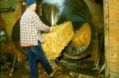 |
Batch-fired boilers used to cause many problems when fed with straw of inferior quality and the supply of combustion air was difficult to control. In recent models, however, the control problem has eventually been solved but the water content of the straw must still be kept below 15- l8 %. Today, an efficiency of 75% and a CO content below 0.5% is possible in batch-fired boilers. About l0 years ago, the efficiency was only 35%. |
![]()
AUTOMATICALLY FIRED BOILERS
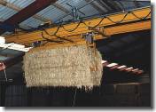 Interest
in
automatically fired boilers is due to the large amount of labour needed
when
operating small bale boilers with batch firing which used to be very
popular.
Several types of automatic boiler plants have been developed but they
all
include a dosing device which automatically feeds the straw into the
boiler
continuously. The dosing device may be designed for whole bales, cut
straw or
straw pellets.
Interest
in
automatically fired boilers is due to the large amount of labour needed
when
operating small bale boilers with batch firing which used to be very
popular.
Several types of automatic boiler plants have been developed but they
all
include a dosing device which automatically feeds the straw into the
boiler
continuously. The dosing device may be designed for whole bales, cut
straw or
straw pellets.
BOILERS FOR BALES OF STRAW
Units consisting of a
scarifier/cutter have been developed which separate the bales, parting
them
into pieces of varying sizes. The bales are fed into this unit on a
conveyor.
The volume of straw treated is often regulated by merely modifying the
velocity
of the conveyor. The straw is transported from the scarifier/cutter by
worm
conveyors or blowers. If blowers are used, the distance to the boiler
can be
greater than with worms but this equipment also consumes more energy.
The scarifier does not actually cut or shred the straw but it
separates the
straw into the segments it was compacted into by the piston of the
baler. In
order to ensure a steady flow of straw through the transport system,
the
scarifier usually has a retaining device. Most scarifiers have knives
to loosen
the straw without creating large lumps.
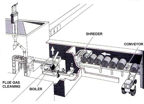
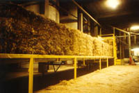 |
In automatically fired boilers, combustion takes places as the straw is fed into the boiler. The air supply is adapted to the straw volume by means of an adjustable damper on a blower. This ensures a good combustion, a significantly improved utilization factor, and a corresponding reduction of particle emission problems as compared with the first manually fired boilers without air regulating devices. Straw ignites easily in an automatic boiler because fresh straw is supplied continuously. |
BOLLERS FOR STRAW PELLETS
The use of straw pellets
for energy production is growing in recent years.
Until now, only small quantities of straw pellets have been produced.
Of
interest is the homogeneous and handy nature of this fuel which makes
it
perfect for transport in tankers and for use in automatic heating
plants.
There are, however, still unsolved slag problems when the pellets are
used in
small boilers. The possibility of establishing a sales network for
rural
districts and villages is being considered in some developed countries.
Pellet-fed plants are usually intended for domestic heating and they
consist of
a boiler and a closed magazine for fuel (straw pellets). A stoker worm
feeds
the fuel into a hearth located in the boiler.
When the plant is operating, the stoker worm works intermittently and
the
feeding capacity is regulated by adjusting its on/off intervals.
Combustion air
is supplied by a blower. The amount of ash from a small straw-fired
boiler is
typically 4% by weight of the straw used.
![]()
 |
Open fire used for cooking in the millions of rural homes transfers heat to a pot poorly. As little as 10 percent of the heat goes to the cooking utensil; the rest is released to the environment. |
Fuel-efficient cook stoves
The most immediate way
to decrease the use of wood as cooking fuel is to introduce improved
wood- and
charcoal-burning cook stoves. Simple stove models already in use can
halve the
use of firewood. A concerted effort to develop more efficient models
might
reduce this figure to 1/3 or 1/4, saving more forests than all of the
replanting efforts planned for the rest of the century. Using simple
hearths
such as those used in India, Indonesia, Guatemala and elsewhere,
one-third as
much wood would provide the same service. These clay “cookers” are
usually
built on the spot with a closed hearth, holes in which to place the
vessels to
be heated, and a short chimney for the draught. Their energy yield
varies,
depending on the model, between approximately 15 and 25%. If these
“cookers”
were used throughout the Sahel, firewood consumption would be reduced
by
two-thirds: 0,2 m3 instead of 0,6 m3 per person per year. There are
clear
benefits of improved cook stoves to the individual family, the local
community,
the nation and the global community.
They include:
![]() Less time
spent
gathering wood or less money spent on fuel, less smoke in the kitchen;
lessening
of respiratory problems associated with smoke inhalation, less manure
used as
fuel, releasing more fertilizer for agriculture,little initial cost
compared to
most other kinds of cookers, improved hygiene with models that
raise
cooking off the floor, safety: fewer burns from open flames; less
chance
of children falling into the fire or boiling pots; if pots are securely
set into
the stove, less chance of children pulling them down on themselves,
cooking
convenience: stoves (and be made to any height and can have work space
on the
surface, the fire requires less attention, as stoves with damper
control
can be easier to tend.
Less time
spent
gathering wood or less money spent on fuel, less smoke in the kitchen;
lessening
of respiratory problems associated with smoke inhalation, less manure
used as
fuel, releasing more fertilizer for agriculture,little initial cost
compared to
most other kinds of cookers, improved hygiene with models that
raise
cooking off the floor, safety: fewer burns from open flames; less
chance
of children falling into the fire or boiling pots; if pots are securely
set into
the stove, less chance of children pulling them down on themselves,
cooking
convenience: stoves (and be made to any height and can have work space
on the
surface, the fire requires less attention, as stoves with damper
control
can be easier to tend.
![]() Stove
building may
create new jobs, potential for using local materials and potential for
local
innovations, money and time saved can be invested elsewhere in the
community.
Stove
building may
create new jobs, potential for using local materials and potential for
local
innovations, money and time saved can be invested elsewhere in the
community.
![]() Lowered
rate of
deforestation improves climate, wood supply and hydrology; decreases
soil
erosion, potential for reducing dependence on imported fuel.
Lowered
rate of
deforestation improves climate, wood supply and hydrology; decreases
soil
erosion, potential for reducing dependence on imported fuel.
COOKING WITH RETAINED HEAT
In regions where much of
the daily cooking involves a longer cooking times (required for many
beans,
grains, stews and soups) the amount of fuel needed to complete the
cooking
process can be greatly reduced by cooking with retained heat. This is a
practice of ancient origin which is still used in some parts of the
world
today.
In some areas a pit is dug and lined with rocks previously heated in
a fire.
The food to be cooked is placed in the lined pit, often covered with
leaves,
and the whole is covered by a mound of earth. The heat from the rocks
is
retained by the earth insulation, and the food cooks slowly over time.
Another version of this method consists of digging a pit and lining
it with
hay or another good insulating material. A pot of food which has
previously
been heated up to a boil is placed in the pit, covered with more hay
and then
earth, and allowed to cook slowly with the retained heat.
![]()
THE HAYBOX COOKER
This latter method is the direct ancestor of the Haybox Cooker,
which is
simply a well insulated box lined with a reflective material into which
a pot of
food previously brought to a boil is placed. The food is cooked in 3 to
6 hours
by the heat retained in the insulated box. The insulation greatly slows
the loss
of conductive heat, convective heat in the surrounding air is trapped
inside the
box, and the shiny lining reflects the radiant heat back into the pot.
Simple haybox style cookers could be introduced along with
fuel-saving cook
stoves in areas where slow cooking is practised. How these boxes should
be made,
and from what materials, is perhaps best left to people working in each
region.
Ideally, of course, they should be made of inexpensive, locally
available
materials and should fit standard pot sizes used in the area.
BUILDING INSTRUCTIONS
There are several principles which should be kept in mind in regard
to the
construction of a haybox cooker:
![]() Insulation should
cover an six sides of the box (especially the bottom and lid). If one
or more
sides are not insulated, heat will be lost by conduction through the
uninsulated
sides and much efficiency will be lost.
Insulation should
cover an six sides of the box (especially the bottom and lid). If one
or more
sides are not insulated, heat will be lost by conduction through the
uninsulated
sides and much efficiency will be lost.
![]() The box
should be
airtight. If it is not airtight, heat will be lost through warm air
escaping by
convection out of the box.
The box
should be
airtight. If it is not airtight, heat will be lost through warm air
escaping by
convection out of the box.
![]() The inner
surfaces
of the box should be of a heat reflective material (such as aluminium
foil) to
reflect radiant heat from the pot back to it.
The inner
surfaces
of the box should be of a heat reflective material (such as aluminium
foil) to
reflect radiant heat from the pot back to it.
A simple, lightweight haybox can be made from a 60 by 120 cm sheet of rigid foil-faced insulation and aluminium tape. Haybox cookers can also be constructed as a box-in-a-box with the intervening space filled with any good insulating material. The required thickness of the insulation will vary with how efficient it is (see below).
|
|
|
|
|
|
|
|
|
|
|
|
|
|
|
|
|
|
|
|
|
|
|
|
|
|
|
INSTRUCTIONS FOR USE
There are some adjustments involved in cooking with haybox cookers:
![]() Less
water should
be used since it is not boiled away.
Less
water should
be used since it is not boiled away.
![]() Less
spicing is
needed since the aroma is not boiled away.
Less
spicing is
needed since the aroma is not boiled away.
![]() Cooking
must be
started earlier to give the food enough time to cook at a lower
temperature than
over a stove.
Cooking
must be
started earlier to give the food enough time to cook at a lower
temperature than
over a stove.
![]() Haybox
cookers
work best for large quantities (over 4 lifers) as small amounts of food
have
less thermal mass and cool faster than a larger quantity. Two or more
smaller
amounts of food may be placed in the box to cook simultaneously.
Haybox
cookers
work best for large quantities (over 4 lifers) as small amounts of food
have
less thermal mass and cool faster than a larger quantity. Two or more
smaller
amounts of food may be placed in the box to cook simultaneously.
![]() The food
should
boil for several minutes before being placed in the box. This ensures
that all
the food is at boiling temperature, not just the water.
The food
should
boil for several minutes before being placed in the box. This ensures
that all
the food is at boiling temperature, not just the water.
The boxes perform best at low altitudes where boiling temperature is highest. They should not be expected to perform as well at high altitudes. One great advantage of haybox cookers is that the cook no longer has to keep up a fire or watch or stir the pot once it’s in the box. In fact, the box should not be opened during cooking as valuable heat is lost. And finally, food will never burn in a haybox.
SAND/CLAY STOVES: THE
LORENA SYSTEM
The Lorena system involves building a solid sand/clay block, then
carving out
a firebox and flue tunnels. The block is an integral sand/clay mixture
which,
upon drying, has the strength of a weak concrete (without the cost).
The mixture
contains 2 to 5 parts of sand to 1 part of clay, though the proportions
can
differ widely.
Pure clay stoves crack badly because the clay shrinks as it dries
and expands
when it is heated. Sand/clay stoves are predominantly sand, with merely
enough
clay to glue the sand together. The mix should contain enough clay to
bind the
sand grains tightly together. The sand/clay mixture is strong in
compression,
but resists impact poorly. It is adequately strong in tension if thin
walls are
avoided. Unlike concrete, which works well as a thin shell, the
sand/clay
mixture relies upon mass for tensile strength.
Advantages:
![]() Sand and
clay are
available in most places, and cheap.
Sand and
clay are
available in most places, and cheap.
![]() The
material is
versatile; it can be used to build almost any size or shape of stove.
The
material is
versatile; it can be used to build almost any size or shape of stove.
![]() The tools
required
are simple.
The tools
required
are simple.
![]() Construction of
the stoves requires simple skills.
Construction of
the stoves requires simple skills.
![]() Stoves
are easy to
repair or replace.
Stoves
are easy to
repair or replace.
Disadvantages:
![]() Construction
relies on heavy materials that are not always available at the building
site and
are difficult to transport.
Construction
relies on heavy materials that are not always available at the building
site and
are difficult to transport.
![]() The
stoves are not
transportable.
The
stoves are not
transportable.
![]() Stove
construction
can require several days of hard work.
Stove
construction
can require several days of hard work.
![]() Efficiency of the
stoves relies on the quality of the workmanship in their construction.
Normally,
they can be expected to work well for at least a year, after which they
may need
to be repaired.
Efficiency of the
stoves relies on the quality of the workmanship in their construction.
Normally,
they can be expected to work well for at least a year, after which they
may need
to be repaired.
KENYA STOVE
One of the most successful urban stove projects in the world is the
Kenya
Ceramic Jiko (KCJ) initiative. Over 500,000 stoves of this new improved
design
have been produced and disseminated in Kenya since the mid-1980s
(Davidson and
Karekezi, 1991). Known as the Kenya Ceramic Jiko, KCJ for short, the
improved
stove is made of ceramic and metal components and is produced and
marketed
through the local informal sector. One of the key characteristics of
this
project was its ability to utilize the existing cook stove production
and
distribution system to produce and market the KCJ. Thus, the improved
stove is
fabricated and distributed by the same people who manufacture and sell
the
traditional stove design.
Another important feature of the Kenya stove project is that the KCJ
design
is not a radical departure from the traditional stove. The KCJ is, in
essence,
an incremental development from the traditional all-metal stove. It
uses
materials that are locally available and can be produced locally. In
addition,
the KCJ is well adapted to the cooking patterns of a large majority of
Kenya’s
urban households. In many respects, the KCJ project provides an ideal
case study
of how an improved stove project should be initiated and implemented.
 |
CERAMIC JIKO increases stove efficiency by addition of a ceramic insulating liner (the brown element), which enables 25 to 40 percent of the heat to be delivered to the pot. From 20 to 40 percent of the heat is absorbed by the stove walls or else escapes to the environment. In addition, 10 to 30 percent gets lost as flue gases, such as carbon dioxide. |
 |
The traditional metal stove that the ceramic Jiko replaces delivers only 10 to 20 percent of the heat generated to a pot. Metal stove, a traditional cooking implement, directs only 10 to 20 percent of the heat to a pot. From 50 to 70 percent of the heat is lost through the stove's metal sides, and another 10 to 30 percent escapes as carbon monoxide, methane and other flue gases. |
CHARCOAL PRODUCTION -
PYROLYSIS
The production of charcoal spans a wide range of technologies from
simple and
rudimentary earth kilos to complex, large-capacity charcoal retorts.
The various
production techniques produce charcoal of varying quality. Improved
charcoal
production technologies are largely aimed at attaining increases in the
net
volume of charcoal produced as well as at enhancing the quality
characteristics
of charcoal.
Typical characteristics of good-quality
charcoal:
Ash content : 5 per cent
Fixed carbon content : 75 per cent
Volatiles content : 20 per cent
Bulk density : 250-300 kg/m3
Physical characteristics : Moderately friable
Efforts to improve charcoal production are largely aimed at
optimising the
above characteristics at the lowest possible investment and labour cost
while
maintaining a high production volume and weight ratios with respect to
the wood
feedstock.
The production of charcoal consist of six major stages:
1. Preparation of wood
2. Drying - reduction of moisture content
3. Pre-carbonization - reduction of volatiles
content
4. Carbonization - further reduction of
volatiles
content
5. End of carbonization - increasing the
carbon content
6. Cooling and stabilization of charcoal
The first stage consists of collection and preparation of wood,
the
principal raw material. For small-scale and informal charcoal makers,
charcoal
production is an off-peak activity that is carried out intermittently
to bring
in extra cash. Consequently, for them, preparation of the wood for
charcoal
production consists of simply stacking odd branches and sticks either
cleared
from farms or collected from nearby woodlands. Little time is invested
in the
preparation of the wood. The stacking may, however, assist in drying
the wood
which reduces moisture content thus facilitating the carbonization
process. More
sophisticated charcoal production systems entail additional wood
preparation,
such as debarking the wood to reduce the ash content of the charcoal
produced.
It is estimated that wood which is not debarked produces charcoal with
an ash
content of almost 30 per cent. Debarking reduces the ash content to
between 1
and 5 per cent which improves the combustion characteristics of the
charcoal.
The second stage of charcoal production is carried out at
temperatures
ranging from 110 to 220 degrees Celsius. This stage consists mainly of
reducing
the water content by first removing the water stored in the wood pores
then the
water found in the cell walls of wood and finally chemically-bound
water.
The third stage takes place at higher temperatures of about 170 to
300
degrees and is often called the pre-carbonization stage. In this stage
pyroligneous liquids in the form of methanol and acetic acids are
expelled and a
small amount of carbon monoxide and carbon dioxide is emitted.
The fourth stage occurs at 200 to 300 degrees where a substantial
proportion
of the light tars and pyroligneous acids are produced. The end of this
stage
produces charcoal which is in essence the carbonized residue of wood.
The fifth stage takes place at temperatures between 300 degrees and
a maximum
of about 500 degrees. This stage drives off the remaining volatiles and
increases the carbon content of the charcoal.
The sixth stage involves cooling of charcoal for at least 24 hours
to enhance
its stability and reduce the possibility of spontaneous combustion.
The final stage consists of removal of charcoal from the kiln,
packing,
transporting, bulk and retail sale to customers. The final stage is a
vital
component that affects the quality of the finally-delivered charcoal.
Because of
the fragility of charcoal, excessive handling and transporting over
long
distances can increase the amount of fines to about 40 per cent thus
greatly
reducing the value of the charcoal. Distribution in bags helps to limit
the
amount of fines produced in addition to providing a convenient
measurable
quantity for both retail and bulk sales.
| ADVATAGES OF CHARCOAL: |
 |
Wood
Gasification Basics
Wood gasification is
also called producer gas generation and destructive distillation. The
essence
of the process is the production of flammable gas products from the
heating of
wood. Carbon monoxide, methyl gas, methane, hydrogen, hydrocarbon
gases, and
other assorted components, in different proportions, can be obtained by
heating
or burning wood products in an isolated or oxygen poor environment.
This is
done by burning wood in a burner which restricts combustion air intake
so that
the complete burning of the fuel cannot occur. A related process is the
heating
of wood in a closed vessel using an outside heat source. Each process
produces
different products. If wood were given all the oxygen it needs to burn
cleanly
the by-products of the combustion would be carbon dioxide, water, some
small
amount of ash, (to account for the inorganic components of wood) and
heat. This
is the type of burning we strive for in wood stoves. Once burning
begins though
it is possible to restrict the air to the fuel and still have the
combustion
process continue. Lack of sufficient oxygen caused by restricted
combustion air
will cause partial combustion. In full combustion of a hydrocarbon
(wood is
basically a hydrocarbon) oxygen will combine with the carbon in the
ratio of
two atoms to each carbon atom. It combines with the hydrogen in the
ratio of
two atoms of hydrogen to one of oxygen. This produces CO2 (carbon
dioxide) and
H2O (water). Restrict the air to combustion and the heat will still
allow
combustion to continue, but imperfectly. In this restricted combustion
one atom
of oxygen will combine with one atom of carbon, while the hydrogen will
sometimes combine with oxygen and sometimes not combine with anything.
This
produces carbon monoxide, (the same gas as car exhaust and for
the same
reason) water, and hydrogen gas. It will also produce a lot of other
compounds
and elements such as carbon which is smoke. Combustion of wood is a
bootstrap
process. The heat from combustion breaks down the chemical bonds
between the
complex hydrocarbons found in wood (or any other hydrocarbon fuel)
while the combination
of the resultant carbon and hydrogen with oxygen-combustion-produces
the heat.
Thus the process drives itself. If the air is restricted to combustion
the
process will still produce enough heat to break down the wood but the
products
of this inhibited combustion will be carbon monoxide and hydrogen, fuel
gases
which have the potential to continue the combustion reaction and
release heat
since they are not completely burned yet. (The other products of
incomplete
combustion, predominately carbon dioxide and water, are products of
complete
combustion and can be carried no further.) Thus it is a simple
technological
step to produce a gaseous fuel from solid wood. Where wood is bulky to
handle,
a fuel like wood gas (producer gas) is convenient and can be burned in
various
existing devices, not the least of which is the internal combustion
engine. A
properly designed burner combining wood and air is one relatively safe
way of
doing this. so this water is available to play a part in the
destructive distillation
process. Wood also contains many other chemicals from alkaloid poisons
to
minerals. These also become part of the process.
As a general concept, destructive distillation of wood will produce
methane
gas, methyl gas, hydrogen, carbon dioxide, carbon monoxide, wood
alcohol,
carbon, water, and a lot of other things in small quantities. Methane
gas might
make up as much as 75% of such a mixture. Methane is a simple
hydrocarbon gas
which occurs in natural gas and can also be obtained from anaerobic
bacterial
decomposition as “bio-gas” or “swamp gas”. It has high heat value and
is simple
to handle. Methyl gas is very closely related to methyl alcohol (wood
alcohol)
and can be burned directly or converted into methyl alcohol (methanol),
a high
quality liquid fuel suitable for use in internal combustion engines
with very
small modification. It’s obvious that both of these routes to the
production of
wood gas, by incomplete combustion or by destructive distillation, will
produce
an easily handled fuel that can be used as a direct replacement for
fossil fuel
gases (natural gas or liquefied petroleum gases such as propane or
butane). It
can be handled by the same devices that regulate natural gas and it
will work
in burners or as a fuel for internal combustion engines with some very
important cautions.
Producer Gas Generators
The simplest device is a
tank shaped like an inverted cone (a funnel). A hole at the top which
can be
sealed allows the user to load sawdust into the tank. There is an
outlet at the
top to draw the wood gas off. At the bottom the point of the “funnel”
is opened
and this is where the burning takes place. Once loaded (the natural
pack of the
sawdust will keep it from falling out the bottom) the sawdust is lit
from the
bottom using a device such as a propane torch. The sawdust smoulders
away. The
combustion is maintained by a source of vacuum applied to the outlet at
the
top, such as a squirrel cage blower or an internal combustion engine.
Smoke is
drawn up through the porous sawdust, being partly filtered in the
process, and
exits the burner at the top where it goes on to be further conditioned
and
filtered. The vacuum also draws air in to support the fire. This burner
is
crude and uncontrollable, especially as combustion nears the top of the
sawdust
pile. This can happen rapidly since there is no control to assure that
the
sawdust burns evenly. “Leads” of fire can form in the sawdust reaching
toward
the top surface. Once the fire breaks through the top of the sawdust
the vacuum
applied to the burner will pull large amounts of air in supporting full
combustion and leaning out the value of the producer gas as a fuel.
This
process depends on the poor porosity of the sawdust to control the
combustion
air so chunk wood cannot be used since its much greater porosity would
allow
too much air in and user would achieve full combustion at very high
temperatures rather than the smouldering and the partial combustion
needed.
Such a burner is unsatisfactory for prolonged gas generation but it is
cheap to
build and it will work with a lot of fiddling. For prolonged trouble
free
operation of a wood gas generator the burner unit must have more
complete
control of the combustion air and the fuel feed. There are various ways
to do
this. For example, if the point of above mentioned original funnel
shaped
burner is completely enclosed then control over the air entering the
burner can
be achieved. This configuration will successfully burn much larger
amount of
wood.
Low
Cost Practical Designs of Biogas Technology
DECOMPOSITION
There are two basic type of decomposition or fermentation: natural
and
artificial aerobic decomposition. Anaerobic means in the absence of Air
(Oxygen). Therefore any decomposition or fermentation of organic
material takes
place in the absence of air (oxygen) is known as anaerobic
decomposition or
fermentation. Anaerobic decomposition can also be achieved in two ways
namely, (i)
natural and (ii) artificial.
Digestible Property of Organic Matter
When organic raw materials are digested in an airtight container
only a
certain percentage of the waste is actually converted into Biogas and
Digested
Manure. Some of it is indigestible to varying degree and either gets
accumulated
inside the digester or discharged with the effluent. The digestibility
and other
related properties of the organic matter are usually expressed in the
following
terms:
Moisture
This is the weight of water lost upon drying of organic matter (OM)
at 100
degrees Celsius. This is achieved by
drying
the organic matter for 48 hours in an oven until no moisture is lost.
The
moisture content is determined by subtracting the final (dried) weight
from the
original weight of the OM, taken just before putting in the oven.
Total Solids (TS)
The TS is the “Dry
Weight” of
the OM (Note: after the sun drying the weight of OM still contains
about 20%
moisture). A figure of 10% TS means that 100 grams of sample will
contain
10 grams of
moisture and 90 grams of dry weight. The Total Solids (TS) consists of
Digestible
Organic (or Volatile Solids) and the indigestible solid (Ash).
Volatile Solids (VS)/ Volatile Matter (VM)
The weight of burned-off organic matter when “Dry Matter” or
“Total
Solids” is heated at a temperature of 550 degrees Celsius for about 3
hours is known as Volatile
Solids (VS)
or Volatile Matter (VM). Muffle Furnace is used for heating the Dry
Matter or
Total Solids of the OM at this high temperature after which only ash
(inorganic
matter) remains. In other wards the Volatile Solids (VS) is that
portion of the
Total Solids (TS) which volatilizes when it is heated at 550 degrees
Celsius and
the inorganic material left after heating of OM at this temperature is
know as
Fixed Solids or Ash. It is the Volatile Solids fraction of the
Total Solids which is converted by bacteria (microbes) in to biogas.
Fixed Solids (FS) or Ash
The weight of matter remaining after the sample is heated at 550
degrees
Celsius is known as Fixed Solids or ash. The Fixed Solids is
biologically
inert material and is also known as Ash.
Biogas Production System
The biogas (mainly mixture of methane and carbon dioxide) is
produced/generated under both, natural and artificial conditions.
However for economically-viable production of biogas for wider
application
the
artificial system is the best and most convenient method. The
production of
biogas is a biological process which takes place in the absence of air
(oxygen),
through which the organic material is converted in to, essentially
Methane (CH4)
and Carbon dioxide (CO2) and the process gives excellent organic
fertilizer
and humus as the second by-product. The one essential requirement in
producing
biogas is an airtight (air leak-proof) container. Biogas is generated
only when
the decomposition of biomass takes place under the anaerobic
conditions, as the
anaerobic bacteria (microbes) that live without oxygen are responsible
for the
production of this gas through the destruction of organic matter. The
airtight
container used for the biogas production under artificial condition is
known as
digester or reactor.
Composition of Biogas
Biogas is a colourless, odourless, inflammable gas, produced by
organic waste
and biomass decomposition (fermentation). Biogas can be produced from
animal,
human and plant (crop) wastes, weeds, grasses, vines, leaves, aquatic
plants and
crop residues etc. The composition of different gases in biogas :
Methane (CH4):
55-70%
Carbon Dioxide (CO2): 30-45%
Hydrogen Sulphide (H2S): 1-2%
Nitrogen (N2):
0-1%
Hydrogen (H2):
0-1%
Carbon Mono Oxide (CO):Traces
Oxygen (O2):
Traces
![]()
Property of Biogas
Biogas burns with a blue flame. It has a heat value of 23 MJ/m3)
when its methane content is in the range of
60-70%. The
value is directly proportional to the amount of methane content and
this
depends upon the nature of raw materials used in the digestion. Since
the
composition of this gas is different, the burners designed for coal
gas, butane
or LPG when used, as ‘biogas burner’ will give much lower efficiency.
Therefore specially designed biogas burners are used which give a
thermal
efficiency of 55-65%.
Biogas is a very stable gas, which is a non-toxic, colourless,
tasteless and
odourless gas. However, as biogas has a small percentage of Hydrogen
Sulphide,
the mixture may very slightly smell of rotten egg, which is not often
noticeable
especially when being burned. When the mixture of methane and air
(oxygen) burn
a blue flame is emitted, producing large amount of heat energy. Because
of the
mixture of Carbon Dioxide in large quantity the biogas becomes a safe
fuel in
rural homes as will prevent explosion.
A 1 m3 biogas, when burned, will generate heat energy sufficient
to bring
approx. 100 litre of water from 20 degrees Celsius to a boil, or
light a
lamp with a brightness equivalent to 60-100 Watts for 4-5 hours.
Mechanics of Extraction of Biogas
The decomposition process for the formation of
methane from
organic material (biodegradable material) involves a group of organisms
belonging to the family - ‘Methane Bacteria’ and is a complex
biological
and
chemical process. The biogas production involves two major processes
consisting
of acid formation (liquefaction) and gas formation (gasification).
However
scientifically speaking these two broad process can further be divide,
which
gives four stages of anaerobic fermentation inside the digester-they
are (i)
Hydrolysis, (ii) Acidification, (iii) Hydrogenation and (iv) Methane
Formation.
At the same time for all practical purposes one can take the methane
production
cycle as a three stage activity- namely, (i) Hydrolysis, (ii)
Acidification and
(iii) Methane formation.
Two groups of bacteria work on the substrate (feedstock) inside the
digester-they are (i) Non-methanogens and (ii) Methanogens. Under
normal
conditions, the non-methanogenic bacteria (microbes) can grow at a pH
range of
5,0 - 8,5 and a temperature range of 25-42 deg. ;whereas,
methanogenic
bacteria can ideally grow at a pH range of 6.5-7.5 and a temperature
range of
25-35 degrees Celsius. These methanogenic bacteria are known as
‘Mesophillic
Bacteria’ and are found to be more flexible and useful in case of
simple
household digesters, as they can work under a broad range of
temperature, as low
as 15 degrees Celsius to as high as 40 degrees Celsius. However their
efficiency
goes down considerably if the slurry temperature goes below 20 degrees
Celsius
and almost stop functioning at a slurry temperature below 15 degrees
Celsius.
Due to this Mesophillic Bacteria can work under all the three
temperature zones
of e.g. India, without having to provide either heating system in the
digester or
insulation in the plant, thus keeping the cost of family size biogas
plants at
an affordable level.
There are other two groups of anaerobic bacteria-they are (i)
Pyscrophillic
Bacteria and (ii) Thermophillic Bacteria. The group of Pyscrophillic
Bacteria
work at low temperature, in the range of 10-15 degrees Celsius but the
work is
still going on to find out the viability of these group of bacteria for
field
applications. The group of Thermophillic Bacteria work at a much higher
temperature, in the range of 45-55 degrees Celsius and are very
efficient,
however they are more useful in high rate digestions (fermentation),
especially
where a large quantity of effluent is already being discharged at a
higher
temperature. As in both the cases the plant design needs to be
sophisticated
therefore these two groups of Bacteria (Pyscrophillic &
Thermophillic) are
not very useful in the case of simple Indian rural biogas plant.
![]()
Biogas Plant
Biogas Plant (BGP) is an airtight container that facilitates
fermentation of
material under anaerobic condition. The other names given to this
device are ‘Biogas
Digester’, ‘Biogas Reactor’, ‘Methane Generator’ and ‘Methane
Reactor’. The recycling and treatment of organic wastes (biodegradable
material) through Anaerobic Digestion (Fermentation) Technology not
only
provides biogas as a clean and convenient fuel but also an excellent
and
enriched bio-manure. Thus the BGP also acts as a miniature
Bio-fertilizer
Factory hence some people prefer to refer it as ‘Biogas Fertilizer
Plant’ or
‘Bio-manure Plant’. The fresh organic material (generally in a
homogenous
slurry form) is fed into the digester of the plant from one end, known
as Inlet
Pipe or Inlet Tank. The decomposition (fermentation) takes place inside
the
digester due to bacterial (microbial) action, which produces biogas and
organic
fertilizer (manure) rich in humus & other nutrients. There is a
provision
for storing biogas on the upper portion of the BGP. There are some BGP
designs
that have Floating Gasholder and others have Fixed Gas Storage Chamber.
On the
other end of the digester Outlet Pipe or Outlet Tank is provided for
the
automatic discharge of the liquid digested manure.
Components of Biogas Plant
The major components of BGP are - (i) Digester, (ii) Gasholder or
Gas Storage
Chamber, (iii) Inlet, (iv) Outlet, (v) Mixing Tank and (vi) Gas Outlet
Pipe.
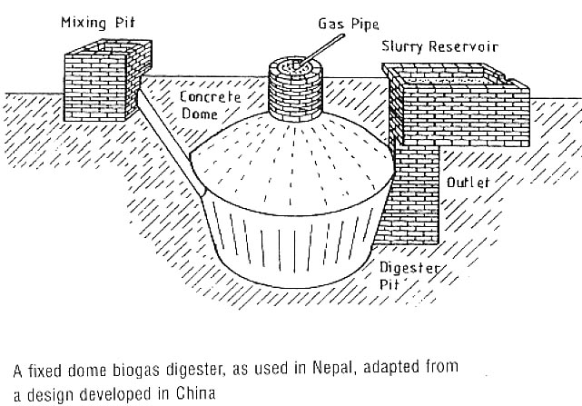
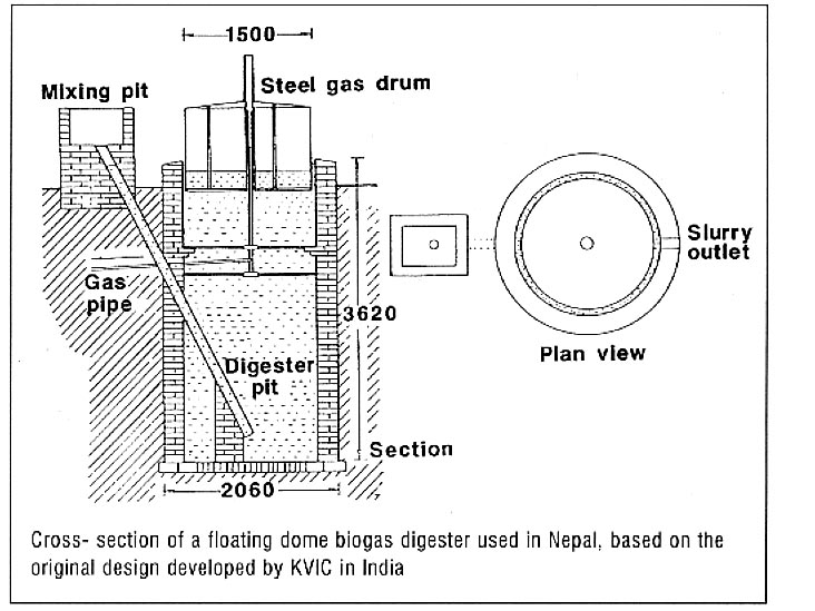
DIGESTER
It is either an under ground Cylindrical-shaped or
Ellipsoidal-shaped
structure where the digestion (fermentation) of substrate takes place.
The
digester is also known as ‘Fermentation Tank or Chamber’. In a simple
Rural
Household BGP working under ambient temperature, the digester
(fermentation
chamber) is designed to hold slurry equivalent to of 55, 40 or 30 days
of daily
feeding. This is known as Hydraulic Retention Time (HRT) of BGP. The
designed
HRT of 55, 40 and 30 days is determined by the different temperature
zones in country like India. The digester can be constructed of
brick
masonry, cement concrete or reinforced cement concrete or
stone
masonry or pre-fabricated cement concrete blocks or
Ferro-cement
(ferroconcrete) or steel or rubber or bamboo reinforced cement mortar.
In
the case of smaller capacity floating gasholder plants of 2 & 3 m3
no
partition wall is provided inside the digester, whereas the BGPs of 4
m3
capacity and above have been provided partition wall in the middle.
This is
provided for preventing short-circuiting of slurry and promoting better
efficiency. This means the partition wall also divides the entire
volume of the
digester (fermentation chamber) into two halves. As against this no
partition
wall is provided inside the digester of a fixed dome design. The reason
for this
is that the diameter of the digesters in all the fixed dome models are
comparatively much bigger than the floating drum BGPs, which takes care
of the
short-circuiting problems to a satisfactory level, without adding to
additional
cost of providing a partition wall.
![]()
GAS HOLDER OR GAS STORAGE CHAMBER
In the case of floating gas holder BGPs, the gas holder is a drum
like
structure, fabricated either of mild steel sheets or ferro-cement
(ferroconcrete) or high density plastic or fibre glass reinforced
plastic . It fits like a cap on the mouth of digester where it is
submerged in the
slurry and rests on the ledge, constructed inside the digester for this
purpose.
The drum collects gas, which is produced from the slurry inside the
digester as
it gets decomposed, and rises upwards, being lighter than air. To
ensure that
there is enough pressure on the stored gas so that it flows on its own
to the
point of utilisation through pipeline when the gate valve is open, the
gas is
stored inside the gas holder at a constant pressure of 8-10 cm of water
column.
This pressure is achieved by making the weight of biogas holder as
80-100
kg/cm2. In its up and down movement the drum is guided by a central
guide pipe.
The gas formed is otherwise sealed from all sides except at the bottom.
The scum
of the semidried mat formed on the surface of the slurry is broken
(disturbed)
by rotating the biogas holder, which has scum-breaking arrangement
inside it.
The gas storage capacity of a family size floating biogas holder BGP is
kept as
50% of the rate capacity (daily gas production in 24 hours). This
storage
capacity comes to approximately 12 hours of biogas produced every day.
In the case of fixed dome designs the biogas holder is commonly
known as gas
storage chamber (GSC). The GSC is the integral and fixed part of the
Main Unit
of the Plant in the case of fixed dome BGPs. Therefore the GSC of
the
fixed dome BGP is made of the same building material as that of the Main
Unit
of the Plant. The gas
storage capacity of a family size fixed dome BGP is kept as 33% of the
rate
capacity (daily gas production in 24 hours). This storage capacity
comes to
approximately 8 hours of biogas produced during the night when it is
not in use.
INLET
In the case of floating biogas holder pipe the Inlet is made of
cement
concrete pipe. The Inlet Pipe reaches the bottom of the digester
well on
one side of the partition wall. The top end of this pipe is connected
to the
Mixing Tank.
In the case of the first approved fixed dome models (Janata Model)
the inlet
is like a chamber or tank-it is a bell mouth shaped brick masonry
construction
and its outer wall is sloppy. The top end of the outer wall of the
inlet chamber
has an opening connecting the mixing tank, whereas the bottom portion
joins the
inlet gate. The top (mouth) of the inlet chamber is kept covered with
heavy
slab. The Inlet of the other fixed dome models (Deenbandhu and Shramik
Bandhu)
has Asbestos Cement Concrete pipes of appropriate diameters.
OUTLET
In the case of floating gas holder pipe the Outlet is made of cement
concrete pipe standing at an angle, which reaches the bottom of the
digester on the
opposite side of the partition wall. In smaller plants (2 & 3 m3
capacity
BGPs) which has no partition walls, the outlet is made of small
(approx. 50 cm
length) cement concrete pipe inserted on top most portion of the
digester,
submerged in the slurry.
In the two fixed dome (Janata & Deenbandhu models) plants, the
Outlet is
made in the form of rectangular tank. However, in the case of Shramik
Bandhu
model the upper portion of the Outlet (known as Outlet Displacement
Chamber) is
made hemi-spherical in shape, designed to save in the material and
labour cost.
In all the three-fixed dome models (Janata, Deenbandhu & Shramik
Bandhu
models), the bottom end of the outlet tank is connected to the outlet
gate.
There is a small opening provided on the outer wall of the outlet
chamber for
the automatic discharge of the digested slurry outside the BGP, equal
to
approximately 80-90% of the daily feed. The top mouth of the outlet
chamber is
kept covered with heavy slab.
![]()
MIXING TANK
This is a cylindrical tank used for making homogenous slurry by
mixing the
manure from domestic farm animals with appropriate quantity of water.
Thoroughly
mixing of slurry before releasing it inside the digester, through the
inlet,
helps in increasing the efficiency of digestion. Normally a feeder fan
is fixed
inside the mixing tank for facilitating easy and faster mixing of
manure with
water for making homogenous slurry.
GAS OUTLET PIPE
The Gas Outlet Pipe is made of GI pipe and fixed on top of the drum
at the
centre in case of floating biogas holder BGP and on the crown of the
fixed dome
BGP. From this pipe the connection to gas pipeline is made for
conveying the gas
to the point of utilisation. A gate valve is fixed on the gas outlet
pipe to
close and check the flow of biogas from plant to the pipeline.
Functioning of a Simple
India Rural
Household Biogas Plants (BGPs)
The fresh organic material (generally in a homogenous slurry form)
is fed
into the digester of the plant from one end, known as Inlet. Fixed
quantity of
fresh material fed each day (normally in one lot at a predetermine
time) goes
down at the bottom of the digester and forms the ‘bottom-most active
layer’,
being heavier then the previous day and older material. The
decomposition
(fermentation) takes place inside the digester due to bacterial
(microbial)
action, which produces biogas and digested or semi-digested organic
material. As
the organic material ferments, biogas is formed which rises to the top
and gets
accumulated (collected) in the Gas Holder (in case of floating gas
holder BGPs)
or Gas Storage Chamber (in case of fixed dome BGPs). A Gas Outlet Pipe
is
provided on the top most portion of the Gas Holder (Gas Storage
Chamber) of the
BGP. Alternatively, the biogas produced can be taken to another place
through
pipe connected on top of the Gas Outlet Pipe and stored separately. The
Slurry
(semi-digested and digested) occupies the major portion of the digester
and the
Sludge (almost fully digested) occupies the bottom most portion of the
digester.
The digested slurry (also known as effluent) is automatically
discharged from
the other opening, known as Outlet, is an excellent bio-fertilizer,
rich in
humus. The anaerobic fermentation increases the ammonia content by 120%
and
quick acting phosphorous by 150%. Similarly the percentage of potash
and several
micro-nutrients useful to the healthy growth of the crops also
increase. The
nitrogen is transformed into Ammonia that is easier for plant to
absorb. This
digested slurry can either be taken directly to the farmer’s field
along with
irrigation water or stored in a Slurry Pits (attached to the BGP) for
drying or
directed to the Compost Pit for making compost along with other waste
biomass.
The slurry and also the sludge contain a higher percentage of nitrogen
and
phosphorous than the same quantity of raw organic material fed inside
the
digester of the BGP.
Type of Digestion
The digestion of organic materials in simple rural household biogas
plants
can be classified under three broad categories. They are:
1. Batch-fed
digestion
2. Semi-continuous digestion and
3. Semi-batch-fed digestion.
BATCH-FED DIGESTION
In batch-fed digestion process, material to be digested is loaded
(with seed
material or innouculam) into the digester at the start of the process.
The
digester is then sealed and the contents left to digest (ferment). At
completion
of the digestion cycle, the digester is opened and sludge (manure)
removed
(emptied). The digester is cleaned and once again loaded with fresh
organic
material, available in the season.
![]()
SEMI-CONTINUOUS DIGESTION
This involves feeding of organic mater in homogenous slurry form
inside the
digester of the BGP once in a day, normally at a fixed time. Each day
digested
slurry; equivalent to about 85-95% of the daily input slurry is
automatically
discharged from the outlet side. The digester is designed in such a way
that the
fresh material fed comes out after completing a cycle (either 55,
40 or 30
days), in the form of digested slurry. In a Semi-continuous digestion
system,
once the process is stabilized in a few days of the initial loading of
the BGP,
the biogas production follows a uniform pattern.
SEMI-BATCH FED DIGESTION
A combination of batch and semi-continuous digestion is known as
Semi-batch
fed Digestion. Such a digestion process is used where the manure from
domestic
farm animals is not sufficient to operate a plant and at the same time
organic
waste like, crop residues, agricultural wastes (paddy & weed
straw), water
hyacinths and weeds etc, are available during the season. In as
Semi-batch fed
Digestion the initial loading is done with green or semi-dry or dry
biomass
(that can not be reduced in to slurry form) mixed with starter and the
digester
is sealed. This plant also has an inlet pipe for daily feeding of
manure slurry
from animals. The Semi-batch fed Digester will have much longer
digestion cycle
of gas production as compared to the batch-fed digester. It is ideally
suited
for the poor peasants having 1-2 cattle or 3-4 goats to meet the major
cooking
requirement and at the end of the cycle (6-9 months) will give enriched
manure
in the form of digested sludge.
Stratification (Layering) of Digester due to Anaerobic
Fermentation
In the process of digestion of feedstock in a BGP many by-products
are
formed. They are biogas, scum, supernatant, digested slurry, digested
sludge and
inorganic solids. If the content of Biogas Digester is not stirred or
disturbed
for a few hours then these by-products get formed into different
layers inside
the digester. The heaviest by-product, which is Inorganic Solids will
be at the
bottom most portion, followed by Digested Sludge.
![]()
SCUM
Mixture of coarse fibrous and lighter material that separates from
the manure
slurry and floats on the top most layer of the slurry is called Scum.
The
accumulation and removal of scum is sometimes a serious problem. In
moderate
amount scum can’t do any harm and can be easily broken by gentle
stirring, but
in large quantity can lead to slowing down biogas production and even
shutting
down the BGPs.
SUPERNATANT
The spent liquid of the slurry (mixture of manure and water)
layering just
above the sludge, in case of Batch-fed and Semi Batch-fed Digester, is
known as
Supernatant. Since supernatant has dissolved solids, the fertiliser
value of
this liquid (supernatant) is as great as that of effluent (digested
slurry).
Supernatant is a biologically active by-product; therefore must be sun
dried
before using it in agricultural fields.
DIGESTED SLURRY (EFFLUENT)
The effluent of the digested slurry is in liquid form and has its
solid
content reduced to approximately 10-20% by volume of
the
original (Influent) manure (fresh) slurry, after going through the
anaerobic
digestion cycle. Out of the three types of digestion processes
mentioned above,
the digested slurry in effluent-form comes out only in semi-continuous
BGP. The
digested slurry effluent, either in liquid-form or after sun drying in
Slurry
Pits makes excellent bio-fertilizer for agricultural and horticultural
crops or
aquaculture.
SLUDGE
In the batch-fed or semi batch-fed digester where the plant wastes
and other
solid organic materials are added, the digested material contains less
effluent and more of sludge. The sludge precipitates at the bottom of
the
digester and is formed mostly of the solids substances of plant wastes.
The
sludge is usually composted with chemical fertilizers as it may contain
higher
percentage of parasites and pathogens and hookworm eggs of etc.,
especially if
the semi-batch digesters are either connected to the pigsty or
latrines.
Depending upon the raw materials used and the conditions of the
digestion, the
sludge contains many elements essential to the plant life e.g.
Nitrogen,
Phosphorous, Potassium plus a small quantity of Salts (trace elements),
indispensable to the plant growth- the trace elements such as boron,
calcium,
copper, iron, magnesium, sulphur and zinc etc. The fresh digested
sludge has high ammonia content and in
this state
may act like a chemical fertiliser by forcing a large dose of nitrogen
than
required by the plant and thus increasing the accumulation of toxic
nitrogen
compounds. For this reason, it is probably best to let the sludge age
for about
two weeks in open place. The fresher the sludge the more it needs to be
diluted
with water before application to the crops, otherwise very high
concentration of
nitrogen my kill the plants.
INORGANIC SOLIDS
In village situation the floor of the animals shelters are full of
dirt,
which gets mixed with the manure. Added to this the collected manure is
kept on
the unlined surface which has plenty of mud and dirt. Due to all this
the feed
stock for the BGP always has some inorganic solids, which goes inside
the
digester along with the organic materials. The bacteria can not digest
the
inorganic solids, and therefore settles down as a part of the bottom
most layer
inside the digester. The Inorganic Solids contains mud, ash, sand,
gravel and
other inorganic materials. The presence of too much inorganic solids in
the
digester can adversely affect the efficiency of the BGP. Therefore to
improve
the efficiency and enhance the life of a semi-continuous BGP it is
advisable to
empty even it in a period of 5-10 years for thoroughly cleaning and
washing it
from inside and then reloading it with fresh slurry.
Classification of Biogas
Plants
The simple rural household BGPs can be classified under the
following broad
categories- (i) BGP with Floating Gas Holder, (ii) BGP with Fixed Roof,
(iii)
BGP with Separate Gas Holder and (iv) Flexible Bag Biogas Plants.
![]()
Biogas Plant with Floating gas Holder
This is one of the common designs in India and comes under the
category of
semi-continuous-fed plant. It has a cylindrical shaped floating biogas
holder on
top of the well-shaped digester. As the biogas is produced in the
digester, it
rises vertically and gets accumulated and stored in the biogas holder
at a
constant pressure of 8-10 cm of water column. The biogas holder is
designed to
store 50% of the daily gas production. Therefore if the gas is not used
regularly then the extra gas will bubble out from the sides of the
biogas
holder.
Fixed Dome Biogas Plant
The plants based on Fixed Dome concept were developed in India in
the
middle
of 1970, after a team of officers visited China. The Chinese fixed dome
plants
use seasonal crop wastes as the major feed stock for feeding,
therefore, their
design is based on principle of ‘Semi Batch-fed Digester’. However, the
Indian Fixed Dome BGPs designs differ from that of Chinese designs, as
the
animal manure is the major substrate (feed stock) used in India.
Therefore all
the Indian fixed dome designs are based on the principle of ‘Semi
Continuous-fed Digester’. While the Chinese designs have no fixed
storage
capacity for biogas due to use of variety of crop wastes as feed stock,
the
Indian household BGP designs have fixed storage capacity, which is 33%
of the
rated gas production per day. The Indian fixed dome plant designs use
the
principle of displacement of slurry inside the digester for storage of
biogas in
the fixed Gas Storage Chamber. Due to this in Indian fixed dome designs
have ‘Displacement
Chamber(s)’, either on both Inlet and Outlet sides (like Janata Model)
or only
on the Outlet Side (like Deenbandhu or Shramik Bandhu Model). Therefore
in
Indian fixed dome design it is essential to keep the combined volume of
Inlet
& Outlet Displacement Chamber(s) equal to the volume of the fixed
Gas
Storage Chamber, otherwise the desired quantity of biogas will not be
stored in
the plant. The pressure developed inside the Chinese fixed dome BGP
ranges from
a minimum of 0 to a maximum of 150 cm of water column. And the maximum
pressure
is normally controlled by connecting a simple Manometer on the pipeline
near the
point of gas utilisation. On the other hand the Indian fixed dome BGPs
are
designed for pressure inside the plant, varying from a minimum of 0 to
a maximum
of 90 cm of water column. The Discharge Opening located on the outer
wall
surface of the Outlet Displacement Chamber and automatically controls
the
maximum pressure in the Indian design.
Biogas Plant with Separate Gas Holder
The digester of this plant is closed and sealed from the top. A gas
outlet
pipe is provided on top, at the centre of the digester to connect one
end of the
pipeline. The other end of the pipeline is connected to a floating
biogas
holder, located at some distance to the digester. Thus unlike the fixed
dome
plant there is no pressure exerted on the digester and the chances of
leakage in
the Main Unit of the Plant are not there or minimised to a very
great
extent. The advantage of this system is that several digesters, which
only
function as digestion (fermentation) chambers (units), can be connected
with
only one large size gas holder, built at one place close to the point
of
utilisation. However, as this system is expensive therefore, is
normally used
for connecting a battery of batch-fed digesters to one common biogas
holder.
Flexible Bag Biogas Plant
The entire Main Unit of the Plant including the digester is
fabricated
out of Rubber, High Strength Plastic, Neoprene or Red Mud Plastic. The
Inlet and
Outlet is made of heavy duty PVC tubing. A small pipe of the same PVC
tubing is
fixed on top of the plant as Gas Outlet Pipe. The Flexible Bag Biogas
Plant is
portable and can be easily erected. Being flexible, it needs to be
provided
support from outside, up to the slurry level, to maintain the shape as
per its
design configuration, which is done by placing the bag inside a pit dug
at the
proposed site. The depth of the pit should as per the height of the
digester
(fermentation chamber) so that the mark of the initial slurry level is
in line
with the ground level. The outlet pipe is fixed in such a way that its
outlet
opening is also in line with the ground level. Some weight has to be
added on
the top of the bag to build the desired pressure to convey the
generated gas to
the point of utilisation. The advantage of this plant is that the
fabrication
can be centralised for mass production, at the district or even at the
block
level. Individuals or agencies having land and some basic
infrastructure
facilities can take up fabrication of this BGP with small investment,
after some
training. However, as the cost of good quality plastic and rubber is
high which
increases the comparative cost of fabricating it. Moreover the useful
working
life of this plant is much less, compared to other Indian simple
Household BGPs,
therefore inspite of having good potential, the Flexible Bag Biogas
Plant has
not been taken up seriously for promotion by the agencies.
![]()
Common Indian Biogas Plant (BGP) Designs
The three of the most common Indian BGP design are:
1. KVIC Model,
2. Janata Model and
3. Deenbandhu Model
The KVIC Model is a floating biogas holder semi continuous-fed BGP and has two types (i) Vertical and (ii) Horizontal. The vertical type is more commonly used and the horizontal type is only used in the high water table region. Though the description of the various components mentioned under this section are common to both the types of KVIC models (Vertical and Horizontal types) some of the details mentioned pertains to Vertical type only. The major components of the KVIC Model are briefly described below:
FOUNDATION
It is a compact base made of a mixture of cement concrete and brick
ballast.
The foundation is well compacted using wooden ram and then the top
surface is
cemented to prevent any percolation & seepage.
Digester (Fermentation Chamber)
It is a cylindrical shaped well like structure, constructed using
the
foundation as its base. The digester is made of bricks and cement
mortar and its
inside walls are plastered with a mixture of cement and sand. The
digester walls
can also be made of stone blocks in places where it is easily available
and
cheap instead of bricks. All the vertical types of KVIC Model of 4 M3
capacity
and above have partition wall inside the digester.
GAS HOLDER
The biogas holder drum of the KVIC model is normally made of mild
steel
sheets. The biogas holder rests on a ledge constructed inside the walls
of the
digester well. If the KVIC model is made with a water jacket on top of
the
digester wall, no ledge is made and the drum of the biogas holder is
placed
inside the water jacket. The biogas holder is also fabricated out of
fibre glass
reinforced plastic, high-density polyethylene or
Ferroconcrete.
The biogas holder floats up and down on a guide pipe situated in the
centre of
the digester. The biogas holder has a rotary movement that helps in
breaking the
scum-mat formed on the top surface of the slurry. The weight of the
biogas
holder is 8-10 kg/m2 so that it can stores biogas at a constant
pressure of 8-10
cm of water column.
INLET PIPE
The inlet pipe is made out of Cement Concrete or Asbestos
Cement
Concrete or Pipe. The one end of the inlet pipe is connected to
the Mixing
Tank and the other end goes inside the digester on the inlet side of
the
partition wall and rests on a support made of bricks of about 1 feet
height.
OUTLET PIPE
The outlet pipe is made out of Cement Concrete or Asbestos
Cement
Concrete or Pipe. The one end of the outlet pipe is connected to
the
Outlet Tank and the other end goes inside the digester, on the outlet
side of
the partition wall and rests on a support made of bricks of about 30 cm
height.
In the case KVIC model of 3 m3 capacity and below, there is no
partition wall,
hence the outlet pipe is made of short and horizontal, which rest fully
immersed
in slurry at the top surface of the digester.
BIOGAS OUTLET PIPE
The Biogas Outlet Pipe is fixed on the top middle portion of the
biogas
holder, which is made of a small of pipe fitted with socket and a
Gate Valve.
The biogas generated in the plant and stored in the biogas holder is
taken
through the gas outlet pipe via pipeline to the place of utilisation.
![]()
Foundation
The foundation is well-compacted base of the digester, constructed
of brick
ballast and cement concrete. The upper portion of the foundation has a
smooth
plaster surface.
Digester
The digester is a cylindrical tank resting on the foundation. The
top surface
of the foundation serves as the bottom of the digester. The digester
(fermentation chamber) is constructed with bricks and cement mortar.
The
digester wall has two small rectangular openings at the middle,
situated
diametrically opposite, known as inlet and outlet gate, one for the
inflow of
fresh slurry and the other for the outflow of digested slurry. The
digester of
Janata BGP comprises the fermentation chamber (effective digester
volume) and
the gas storage chamber.
Gas Storage Chamber
The Gas Storage Chamber is also cylindrical in shape and is
the
integral part of the digester and located just above the fermentation
chamber.
The Gas Storage Chamber is designed to store 33%
(approx. 8 hours) of the daily gas
production
from the plant. The Gas Storage Chamber is constructed with
bricks and
cement mortar. The gas pressure in Janata model varies from a minimum
of 0 cm
water column (when the plant is completely empty) to a maximum of up to
90 cm of
water column when the plant is completely full of biogas.
Fixed Dome Roof
The hemi-spherical shaped dome forms the cover (roof) of the
digester and
constructed with brick and cement concrete mixture, after which it is
plastered
with cement mortar. The dome is only an enclosed roof designed in such
a way to
avoid steel reinforcement. (Note: The gas collected in the dome of a
Janata
plant is not under pressure therefore can not be utilised. It is only
the gas
stored in the Gas Storage Chamber portion of the digester and
that is
under pressure and can be said as utilisable biogas).
Inlet Chamber
The upper portion of the Inlet Chamber is in the shape of bell mouth
and
constructed using bricks and cements mortar. Its outer wall is kept
inclined to
the cylindrical wall of the digester so that the feed material can flow
easily
into the digester by gravity. The bottom opening of the Inlet Chamber
is
connected to the Inlet Gate and the upper portion is much wider and
known as
Inlet Displacement Chamber. The top opening of the inlet chamber
is
located close to the ground level to enable easy feeding of fresh
slurry.
Outlet Chamber
It is a rectangular shaped chamber located just on the opposite side
of the
inlet chamber. The bottom opening of the Outlet Chamber is connected to
the
Outlet Gate and the upper portion is much wider and known as Outlet
Displacement
Chamber. The Outlet Chamber is constructed using bricks and
cement mortar.
The top opening of the Outlet Chamber is located close to the ground
level to
enable easy removal of the digested slurry through a discharge opening.
The
level of the discharge opening provided on the outer wall of the outlet
chamber
is kept at a somewhat lower level than the upper mouth of the inlet
opening, as
well as kept lower than the Crown of the Dome ceiling. This is to
facilitate
easy flow of the digested slurry out the plant in to the digested
slurry pit and
also to prevent reverse flow, either in the mixing tank through inlet
chamber or
to go inside the gas outlet pipe and choke it.
Biogas Outlet Pipe
The Biogas Outlet Pipe is fixed at the crown of the dome, which is
made of a
small length of pipe fitted with socket and a Gate Valve.
![]()
Deenbandhu
Model
The Deenbandhu Model is a semi continuous-fed fixed dome Biogas
plant. While
designing the Deenbandhu model an attempt was made to minimise the
surface
area of the BGP with a view to reduce the installation cost, without
compromising on the efficiency. The design essentially consists of
segments of
two spheres of different diameters joined at their bases. The structure
thus
formed comprises of (i) the digester (fermentation chamber), (ii) the
gas
storage chamber, and (iii) the empty space just above the gas storage
chamber.
The higher compressive strength of the brick masonry and concrete makes
it
preferable to go in for a structure that could be always kept under
compression.
A spherical structure loaded from the convex side will be under
compression and
therefor, the internal load will not have any effect on the structure.
The digester of the Deenbandhu BGP is connected with the Inlet Pipe
and the
Outlet Tank. The upper part (above the normal slurry level) of the
outlet tank
is designed to accommodate the slurry to be displaced out of the
digester
(actually from the gas storage chamber) with the generation and
accumulation of
biogas and known as the Outlet Displacement Chamber. The Inlet
Pipe of the
Deenbandhu BGP replaces the Inlet Chamber of Janata Plant. Therefore to
accommodate all the slurry displaced out from the Gas Storage Chamber,
the
volume of the Outlet Chamber of Deenbandhu model is twice the volume of
the Outlet
Tank of the Janata BGP of the same capacity.
Being a fixed dome technology, the other components and their
functions are
same as in the case of Janata Model BGP and therefore are not
elaborated here
once again.
Shramik Bandhu Model
This new biogas plant model which is also a semi-continuous
hydraulic
digester plant was designed by the author and christened as SHRAMIK
BANDHU. Since then, three more models (rural household
plants)
in the family of SHRAMIK BANDHU Plants have also been developed. The
second one,
a semi-continuous hydraulic digester, works on the principle of
semi-plug flow
digester (suitable for use as a Night Soil based or Toilet attached
plant). The
third one uses simple low cost anaerobic bacterial filters, designed
for
possible application as a low cost and low maintenance wastewater
treatment system. The fourth one is a semi-batch fed hydraulic
digester, ideally
suitable
for the regions where plenty of seasonal crop wastes and waste green
biomass are
available and population of domestic farm animals are less, for
producing the
desired quantity of biogas from it alone.
The family of SHRAMIK BANDHU biogas plants designs uses the fixed
dome
concepts as in the case of pervious two most popular Indian fixed dome
plants,
namely, Janata and Deenbandhu models. In other words, all the four
Models of the
family of SHRAMIK BANDHU Plant have both, (i) the Gas Storage Chamber
(GSC) and
(ii) the Dome shaped Roof. However, in this section, the description
about
Shramik Bandhu plants relates to SBP-I model only.
The SHRAMIK BANDHU Plant is made of Bamboo Reinforced Cement
Mortar,
by pre-fabricated bamboo shells, using the correct size mould for a
given
capacity SBP-I model- Thus, completely replacing the bricks. These
bamboo shells
are made by weaving bamboo strips (weaving of which can be done in the
village
itself) for casting a Bamboo Reinforced Cement
Mortar structure. The Bamboo Reinforced Cement
Mortar structures on the one
hand are
used for giving the right shape to this plant, while on the other hand
acts as
the reinforcement to the cement mortar plaster as it is casted more or
less like
the ferro-cement structure. In order to protect the bamboo strips from
microbial
attack, they are pre-treated by immersing them in water mixed with
prescribed
ratio of Copper Sulphate (CuSO4) for a minimum of 24 hours before
weaving of
shell structure is done. As a further safety measure DPC powder in
appropriate
quantity is mixed while doing second layer (coat) of smooth plastering
on the
Main Unit of the Plant, Outlet Chamber ; as well as other
Bamboo Reinforced Cement
Mortar
components and sub-components, to make the entire structure of SBP-I
moisture
proof. The Shramik Bandhu plant made from Bamboo Reinforced
Cement
Mortar would be much stronger
because it
has both higher tensile, as well as compressive strength, as compared
to either
First Class Bricks or Cement Concrete or Cement Mortar , when
used
alone. The reason for this is that the bamboo shell structures used
(for both
reinforcement and shape of the plant) for the construction of Shramik
Bandhu
plant is made by weaving strips [only the outer harder surface (skin)
and not
the softer inner part of bamboo] from seasoned (properly cured) bamboo.
Therefore, the entire structure (body) of the SBP-I model would be very
strong,
durable and have long useful working life. The two previous fixed dome
models,
namely Janata and Deenbandhu model have no reinforcement and are made
of Bricks
and Cement Mortar only, therefore, while they are very strong under
compression
but cannot withstand high tensile force. The hemi-spherical shell
shaped
(structure) of SHRAMIK BANDHU (SBP-I) model loaded from top on its
convex side
will be under compression. However, due to comprehensive strength
provided by
both cement mortar, as well as the reinforcement provided by the woven
bamboo
shell will ensure that the internal and external load will not have any
residual
effects on the structure. The bamboo reinforcement will provide added
strength
(both tensile and compressive) to make the entire structure of SHRAMIK
BANDHU (SBP-I)
model very sound, as compared to the previous two fixed dome Indian
models (Janata
& Deenbandhu), referred above.
The digester of SBP-I model is connected to the slurry mixing tank
with inlet
pipe made of 10 cm (4”) diameter Asbestos Cement Concrete
pipe, for feeding the slurry inside the plant.
The Outlet Displacement Chamber is designed to accommodate the
slurry
to be displaced out of the digester with the generation &
accumulation of
biogas. The Outlet Displacement Chamber of SBP-I model is also
kept
hemi-spherical in shape to reduce it’s surface area for a given volume
(to
save in building materials and time taken for construction. The Outlet
Displacement Chamber is
also
made of Bamboo Reinforced Cement
Mortar, using a hemi-spherical shaped woven bamboo shell
structure.
A Manhole opening of about 60 cm diameter is
provided on
the crown of the hemi-spherical shaped Outlet Displacement
Chamber. The Manhole is big enough
for one
person to go inside and come out, at the same time small enough to be
able to
easily close it by a same size Manhole Cover, which is also made of Bamboo
Reinforced Cement
Mortar.
![]()
Gasification is the
newest method to generate electricity from biomass. Instead of
simply
burning the fuel, gasification captures about 65-70% of the energy in
solid
fuel by converting it first into combustible gases. This gas is
then
burned as natural gas is, to create electricity, fuel a vehicle, in
industrial
applications, or converted to synfuels-synthetic fuels. Since
this is the
latest technology, there is still a lot of researc development going on.
A promising alternative is the gas turbine fuelled by gas produced from
biomass
by means of thermochemical decomposition in an atmosphere that has a
restricted
supply of air. Gas turbines have lower unit-capital costs, can be
considerably
more efficient and have good prospects for improvements of both
parameters.
Biomass gasification systems generally have four principal components:
(a) Fuel preparation, handling
and feed
system;
(b) Gasification reactor
vessel;
(c) Gas cleaning, cooling and
mixing
system;
(d) Energy conversion system
(e.g.,
internal-combustion engine with generator or pump set, or gas burner
coupled to
a boiler and kiln).
When gas is used in an
internal-combustion engine for electricity production (power
gasifiers), it
usually requires elaborate gas cleaning, cooling and mixing systems
with strict
quality and reactor design criteria making the technology quite
complicated.
Therefore, power gasifiers world-wide have had a historical record of
sensitivity to changes in fuel characteristics, technical hitches,
manpower
capabilities and environmental conditions.
Gasifiers used simply for heat generation do not have such complex
requirements
and are, therefore, easier to design and operate, less costly and more
energy- efficient.
All types of gasifiers require feedstocks with low moisture and
volatile
contents. Therefore, good quality charcoal is generally best, although
it requires
a separate production facility and gives a lower overall efficiency.
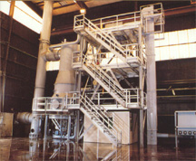 In the simplest,
open-cycle gas turbine the hot exhaust of the turbine, is discharged
directly
to the atmosphere. Alternatively, it can be used to produce steam in a
heat
recovery steam generator. The steam can then be used for heating in a
cogeneration system; for injecting back into the gas turbine, thus
improving
power output and generating efficiency known as a steam-injected gas
turbine
(STIG) cycle; or for expanding through a steam turbine to boost power
output
and efficiency - a gas turbine/steam turbine combined cycle (GTCC).
While
natural gas is the preferred fuel, limited future supplies have
stimulated the
expenditure of millions of dollars in research and development efforts
on the
thermo-chemical gasification of coal as a gas-turbine feedstock. Much
of the
work on coal-gasifier/gas-turbine systems is directly relevant to
biomass
integrated gasifier/gas turbines (BlG/GTs). Biomass is easier to gasify
than
coal and has a very low sulphur content. Also, BIG/GT technologies for
cogeneration or stand-alone power applications have the promise of
being able
to produce electricity at a lower cost in many instances than most
alternatives, including large centralized, coal-fired, steam-electric
power
plants with flue gas desulphurization, nuclear power plants, and
hydroelectric
power plants.
In the simplest,
open-cycle gas turbine the hot exhaust of the turbine, is discharged
directly
to the atmosphere. Alternatively, it can be used to produce steam in a
heat
recovery steam generator. The steam can then be used for heating in a
cogeneration system; for injecting back into the gas turbine, thus
improving
power output and generating efficiency known as a steam-injected gas
turbine
(STIG) cycle; or for expanding through a steam turbine to boost power
output
and efficiency - a gas turbine/steam turbine combined cycle (GTCC).
While
natural gas is the preferred fuel, limited future supplies have
stimulated the
expenditure of millions of dollars in research and development efforts
on the
thermo-chemical gasification of coal as a gas-turbine feedstock. Much
of the
work on coal-gasifier/gas-turbine systems is directly relevant to
biomass
integrated gasifier/gas turbines (BlG/GTs). Biomass is easier to gasify
than
coal and has a very low sulphur content. Also, BIG/GT technologies for
cogeneration or stand-alone power applications have the promise of
being able
to produce electricity at a lower cost in many instances than most
alternatives, including large centralized, coal-fired, steam-electric
power
plants with flue gas desulphurization, nuclear power plants, and
hydroelectric
power plants.
Gasifiers using wood and charcoal (the only fuel adequately proved so
far) are
again becoming commercially available, and research is being carried
out on
ways of gasifying other biomass fuels (such as residues) in some parts
of the
world. Problems to overcome include the sensitivity of power gasifiers
to
changes in fuel characteristics, technical problems and environmental
conditions. Capital costs can still sometimes be limiting, but can be
reduced
considerably if systems are manufactured locally or use local
materials. For
example, a ferrocement gasifier developed at the Asian institute of
Technology
in Bangkok had a capital cost reduced by a factor of ten. For
developing
countries, the sugarcane industries that produce sugar and fuel ethanol
are
promising targets for near-term applications of BIG/GT technologies.
![]()
CO-FIRING
Co-firing of biofuels
(e.g. gasified wood) and coal seems to be the way how to reduce
emissions from
coal firing power plants in many countries. In 1999 a co-firing power
plant -
biomass and coal - started its operation in Zeltweg (Austria). A 10 MW
biomass
gasification unit was installed in combination with an existing coal
fired
power station. The gasifier needs 16 m3 woody biomass (chips and bark)
per
hour. The calorific value of the gas ranges between 2,5 - 5 MJ/Nm3. The
project
named “Biococomb” is an EU demonstration project. It was realised by
the
“Verbund” company together with several other companies from Italy,
Belgium,
Germany and Austria and co-financed by the European Commission.
COGENERATION
Biomass-Fired Gas
Turbine
A current trend in industrialized countries is the use of increasing
number
of smaller and more flexible biomass based plants for cogeneration of
heat and
electricity. Biomass cogeneration plant in Knoxville, Tennessee, USA,
is at the
cutting edge of one of the promising technologies behind this
development. The
plant combines a wood furnace with a gas turbine. A hot, pressurized
flue-gas
filter cleans the exhaust gas from the furnace before it drives the
power
turbine. The plant can run on fresh cut sawdust (40% humidity), and
produces
5.8 MW of electricity, while consuming 10 tons sawdust/hour, and
delivering
heat as hot exhaust gas at 370°C. This gives an electric efficiency
of about
19% and overall efficiency of up to about 75%. The exhaust gas can be
used in a
steam turbine, increasing electric output to 9.6 MW, and electricity
efficiency
to over 30%. The plant in Knoxville has been operating since spring
1999.
![]()
Guideline for Estimation of Biomass Potentials, Barriers and Effects
Unused Forest Energy
Potential &
Fuelwood
Most commercial forests e.g.
in Europe have an unused energy potential, which can be used without
endangering their role in the natural eco-systems. Beside this, most
forests
already have a production of firewood. Mountain forests and other less
commercial forests can in certain cases also deliver wood for energy,
but only
after due environmental consideration.
The available forest
residues are generally branches with diameters smaller than 7 cm.
Generally,
leaves and roots should be left in the forest to preserve a healthy
forest
environment. They are also more difficult to use for energy than
branches.
Energy content
The energy content in
totally dry wood is apr. 5,2 kWh/kg. In normally dry firewood (20%
humidity)
the energy content is apr. 4,2 kWh/kg (lower heating value). In most
statistics,
wood is measured in cubic meter solid wood (with or without bark). The
density
of dry wood varies from 800 kg/m3 for hard leafy wood (e.g. beech) to
600 kg/m3
for coniferous (e.g. pine). This gives energy contents of respectively
3400 and
2500 kWh/m3 for beech and pine (lower heating value, 20% humidity).
For furnaces with flue-gas condensers, the energy output can be
80-90% of
the higher heating value, which is respectively apr. 4% and 10% above
lower
heating values for wood with 20% and 40% humidity.
Resource estimation
The available amount of
wood can be estimated from forest statistics as the difference between
annual
growth (in m3, including bark) and the annual wood extraction for
timber and
other non-energy purposes. Bark can be estimated to 20% of wood
exclusive bark.
Often the statistics provide only commercial extraction, to which
should be
added an estimate of non- commercial use. The non-commercial use is
often in
the form of firewood-gathering by local inhabitants, and could thus be
included
in the energy potential. In reality the resource might be lower than
this
estimate due to problems of extracting all branches and/or due to the
need of
leaving some branches in the forest for ecological reasons. These two
factors
can reduce the resource with as much as 50% even in commercial forests.
If forest statistics are incomplete or unreliable,
simplified estimates can be made:
Use of firewood for
heating does not in general pose barriers. The efficient use of
firewood,
however, requires efficient ovens and basic knowledge of the users.
Using
wood-chips requires equipment for producing the wood- chips, storage,
drying,
and feeding into an appropriate boiler. This production-chain should be
set up
locally for successful use of wood-chips for heating. Wood-chips are
most
suitable in larger boilers, above 100 kW. Often wood-chips have high
humidity
(40 - 60%), and boilers with flue-gas condensation should be preferred.
Effects on economy,
environment and
employment
Economy
Utilization of firewood
and wood-chips is based on a local resource, requires minimal
transport/import
and is therefore quite inexpensive in comparison to fossil fuels.
Price estimates,
excluding transport & profits (of leafy trees, density 760 kg/m3):
Denmark: 240 DKK/m3
equal to 0,11 DKK/kWh (1 EUR = 7,4 DKK). Danish example with Czech
wages: 513 CZK/m3 equal to 0,24 CZK/kWh (1EUR=27 CZK).
Use of wood replacing
fossil fuels reduces net CO2 emissions, because the forest absorbs the
same
quantity of CO2, which is released in the later combustion of the wood.
The
energy to process the wood is in the order of a few percent of its
heating
value.
Wood combustion emits very little sulphur (SO2) compared with coal
and oil.
NOx emissions depend on the combustion process and often the lower
combustion
temperature leads to lower emissions than for coal and oil combustion.
Emissions of particulate and unburned hydrocarbons are totally
dependent on the
combustion processes, and can be a problem in small and badly designed
furnaces. Ashes from the combustion can often be used as fertilizer.
It is important that the extraction of wood is done in a sustainable
manner,
with adequate re-planting etc.
Employment
According to French experience, utilizing of excess energy from
forests
requires 450 jobs/TWh with the degree of mechanization that is normal
for
Western Europe.
Hand-rules
Each ha of forest on
good soil in Central Europe grows 10 tons/ha of wood. If 25% of this is
available as waste-wood for energy, the output for energy is 2,5 tons
or 11 MWh
(20% humidity).
Residues from wood industry
In saw-mills, pulp mills
and all wood processing industries, residues are made that can be used
for
energy purposes. From saw-mills it is mainly bark and saw-dust. From
pulp-mills
(cellulose and paper production) it is black and sulphite liquors as
well as
wood and bark residues. From sawmills comes edgings, chips, sawdust,
bark and
other residues. Some of these residues are used for pulping, and
particle-and
fibreboard. Analysis from several countries show that 30-70% of wood
industry
residues are used for these non-energy purposes.
The residues in forms of larger pieces can be made into wood- chips
for
wood-chip boilers, while sawdust can be burned in special furnaces or
compressed
into wood pellets of brickets that can be used in smaller furnaces and
ovens.
Often wood industry uses their wood residues to meet own energy
demands for
heating, steam and eventually electricity.
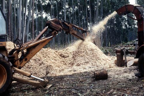
Resource Estimation
Evaluation of wood
residues can be based on trade-statistics of non-energy wood and
wood-products
compared with total extraction from forests. The difference is
available for
energy purposes, and is probably to some extent already used as such in
wood
industries.
As a simple estimate can be used that residues in general are 25-35%
of
total forest removals (e.g. Poland 29%, Canada 29%, Finland 33%, Sweden
36%,
USA 37% from biofuels). If a larger part of forest removals are
exported
without processing, the figure will be lower.
![]()
Barriers
This resource has in
general the fewest barriers of all renewable energies. An efficient
utilization
requires, however, investments in new boilers, or at least in a
pre-combustion
furnace, that can be attached to an existing (good) boiler.
Effect on economy,
environment and
employment
When the residues from
industry are treated as waste without commercial value, the economy of
using
them for energy is almost always cost-effective, and has a better
economy than
wood residues from forests.
Environmental effects
are equal to wood residues from forests, as long as combustion of
chemically
treated and painted wood residues is avoided. Such wood-residues should
be
treated as municipal waste or chemical waste depending on the treatment.
The direct employment of
using industrial wood waste is low because the waste has to be handled
anyway.
Indirectly it gives considerable employment because it turns unused
materials
into a valuable product (energy).
Combustible waste from
agriculture
Straw, prunings of fruit
trees and wine and olive oil residues are all residues from agriculture
that
can be used for energy purposes. Straw harvest is depending on weather
conditions and vary considerably from year to year. The straw surplus
has also
large variations from year to year. If a large part of the surplus is
used, an
alternative fuel should be considered for years with little surplus
straw. Such
an alternative fuel could be wood-chips forest residues, that can be
used
alternatively with straw in many boilers. The forest residues can stay
several
years in the forests before usage. Straw surplus can be ploughed into
the field
for enriching the humus layer of the field. When this is needed for a
sustainable agriculture, the surplus straw for energy will be lower.
Energy Content
The energy content of
straw is 4,9 kWh/kg of dry matter (high heating value). With a typical
of 15%
humidity the lower heating value is 4,1 kWh/kg. The energy in 1 m3 of
densely
compressed straw bales is 500 kWh (density 120 kg/m3).
The average efficiency for 22 straw-fired heating stations in
operation in
Denmark is 80-85%, not including flue-gas condensation.
Resource Estimation
Estimations of straw
production can be obtained from agricultural statistics. This value
should be
reduced with agricultural consumption of straw for animal fodder and
bedding.
The agricultural consumption is very dependent on the type of stables
used. In
Denmark the average available surplus for energy is estimated to 59% of
which
1/5 is already used, mainly for heating (Straw). In Eastern Bohemia,
this
surplus is estimated to about 35%. As a general, conservative estimate
for
Europe 25% of the straw production can be used for energy. The straw
production
varies +/- 30% from average years to years with high respectively low
straw
harvest.
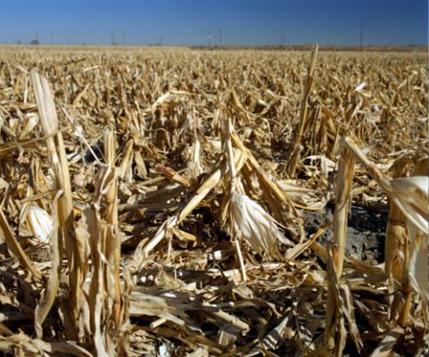
A rough estimate can be made based on agricultural area and a
straw
harvest of 4-7 tons/ha depending on soil, type of grain and weather.
![]()
Barriers
Limited experience and funds for the necessary investments are often
the
largest barriers to use straw for energy. Other barriers can be:
![]() the need
to
develop a market for straw with attractive prices for users as well as
suppliers,
the need
to
develop a market for straw with attractive prices for users as well as
suppliers,
![]() pesticides can in
certain situations give unwanted chlorine compounds in the straw. This
can be
reduced by leving the straw for a period at the field before
collection, so
called wilting.
pesticides can in
certain situations give unwanted chlorine compounds in the straw. This
can be
reduced by leving the straw for a period at the field before
collection, so
called wilting.
![]() use of
straw in
inadequate and polluting boilers can give straw a bad reputation.
use of
straw in
inadequate and polluting boilers can give straw a bad reputation.
Effect on economy,
environment and
employment
Economy
In Denmark, straw-prices
vary from 0,085 DKK/kWh to 0,12 DKK/kWh (1EUR=7,4 DKK) for baled
straw
delivered at a straw-firing station. In Czech Republic the prices for
straw
collected at the farm has been quoted at 0,043 CZK/kWh (1EUR=27 CZK)for
loose
straw and 0,054 CZK/kWh for baled straw.
Costs, average for 16 straw-fired installations in Denmark are per kWh heat produced:
|
|
|
|
| Fuel |
|
|
| Electricity* |
|
|
| O&M, administr. |
|
|
| Capital costs |
|
|
| TOTAL |
|
|
The environmental impact of using agricultural residues are, as for wood, reduced CO2-emission, reduced sulphur emissions, compared with coal and oil. Emissions of particulate, NOx and volatile organic compounds (VOC) depend on furnaces and flue-gas treatment. Chlorine components in straw gives emission of HCl as mentioned above. Danish experience from 13 straw-fires heating stations shows the following emissions (all plants have particulate filters):
|
|
g/kWh straw |
g/kWh straw |
|
|
|
|
|
|
|
|
|
|
|
|
|
|
|
|
|
|
|
|
|
|
|
|
|
|
|
Employment
The direct employment of harvesting straw in a fully mechanized
agriculture
in Denmark is estimated to 350 jobs/TWh. This is for technologies with
large
straw-bales (500 kg each). For a system based on smaller bales (10-20
kg), the
employment is larger.
ENERGY CROPS
It is estimated that
20-40 million hectares of land in the old EU member states will be
surplus to
conventional agricultural requirement. The same situation (agricultural
overproduction and setting the land aside) can be expected in new EU
member
states in Central Europe as well. This set aside land can be used for
different
purposes, one of them is energy crop production.
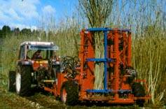
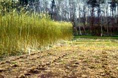 Willows.
Energy Contents and Yields
The following table gives an overview of the expected yields and
energy
contents for three of the promising plants for solid fuel production.
|
(tonnes/ha/year) |
(GJ/dry tonne) |
(GJ/ha/year) |
|
|
|
|
|
|
|
|
|
|
|
|
|
|
|
|
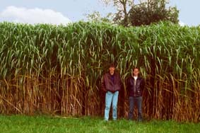 Miscanthus.
Another promising plant is hemp, which has yields up to 24
tonnes/hectare
in approximately 4 month. Hemp plantation is illegal in many countries,
even
though some variants has very little content of cannabis.
![]()
Resource Estimation
The energy potentials
can be estimated from the area of land which is set aside in the
country/region
and can be used for energy plantation and the expected outcome of the
above
crops under the actual climate and soil conditions. In most countries,
national
estimates exists of the different yields of the plants. Using excess
farm land
and ecologically degraded land should be the priority.
Barriers
Short rotation crops may require as much fertilization as
traditional crops
and degraded land must be regenerated before cultivation using
fertilization.
For tree crops these drawbacks may be offset by the fact that they
retain an
active root system throughout the year. Wood ash would be an effective
fertilizer for biofuels plantation, reducing the problems caused by the
leaching
of fertilizers into ground water.
Effect on Economy, Environment and Employment Economy, Costs:
Production costs for Sweet
Sorghum are
50 Euros per dry tonne.
Production cost of Salix are
70 Euros
(500 DKK) / tonne of dry matter in Denmark (Hvidsed).
Electricity generation cost for biomass (Sweet sorghum ) fuelled
system
(1992) and improved systems (2000):
Small facility : 0,16 EURO/kWh
Large facility : 0,08 EURO/kWh
Small improved : 0,07 EURO/kWh
Large improved : 0,05 EURO/kWh
Environment
An important feature for Salix is that it can be used for water
purification
- it is possible to grow Salix in purification systems and in the same
time
harvest the Salix for energy (10-20 tonnes of sludge can be used on
each hectare
every year). Other benefits of biomass for energy plantation includes
forest
fire control, improved erosion control, dust absorption, and used as
replacement
for fossil fuels: no sulphur emission and lower NOx emissions.
Employment
For Sweet Sorghum production cost 50% is manpower cost. Production
of about
500 tonnes of dry biomass per year justifies the creation of one new
job. Other
new jobs could be created in related industries such as composting,
pulp for
paper, service organisation etc.
Hand Rule
|
Annually 90 tonnes of fresh material = 25 tonnes of dry matter per hectare = 450 GJ or 11 tonnes of oil equivalent can be produced. 1/3 as ethanol from sugars and 2/3 of fuel from bagasse. This corresponds to the absorption of 30-45 tonnes of CO2 per hectare and per year. |
BIOGAS
The largest potential for biogas is in manure from agriculture.
Other
potential raw-materials for biogas are:
![]() sludge
from
mechanical and biological waste-water treatment (sludge from chemical
waste-water treatment has often low biogas potential)
sludge
from
mechanical and biological waste-water treatment (sludge from chemical
waste-water treatment has often low biogas potential)
![]() organic
household
waste
organic
household
waste
![]() organic,
bio-degradable waste from industries, in particular slaughter-houses
and
food-processing industries
organic,
bio-degradable waste from industries, in particular slaughter-houses
and
food-processing industries
Care should be taken not to include waste with heavy metals or harmful chemical substances when the resulting sludge is to be used as fertilizer. These kinds of polluted sludge can be used in biogas plants, where the resulting sludge is treated as waste and e.g. incinerated.
Another biogas source is landfills with large amounts of organic waste, where the gas can be extracted directly from drillings in the landfill, so called landfill gas. Such drillings will reduce uncontrolled methane emission from landfills.
Energy Content
The biogas-production
will normally be in the range of 0,3 - 0,45 m3 of biogas (60% methane)
per kg
of solid (total solid, TS) for a well functioning process with a
typical
retention time of 20-30 days at 32 deg.C. The lower heating value of
this gas
is about 6,6 kWh/m3. Often is given the production per kg of volatile
solid (VS),
which for manure without straw, sand or others is about 80% of total
solids
(TS).
A biogas plant have a self-consumption of energy to keep the manure
warm.
This is typically 20% of the energy production for a well designed
biogas
plant. If the gas is used for co-generation, the available electricity
will be
30-40% of the energy in the gas, the heat will be 40-50% and the
remaining 20%
will be self-consumption.
![]()
Resource Estimation
For manure, the available data is often the numbers of livestock.
From this
can be made an estimation of available manure. While the amount of
manure
produced from animals depends on amount and type of fodder, some
average figures
are made for most countries.
The following table shows the figures for Denmark :
|
|
|
(kg/day) |
|
|
(kWh/yr) |
|
|
|
|
|
|
|
|
|
|
|
|
|
|
|
|
|
|
|
|
|
|
|
|
|
|
|
|
|
|
|
|
|
|
|
To make an estimation of the yearly production, it should be evaluated how many days per year the animals are in stables. For large poultry farms and pig-farms it is often the whole year, while cows are in stables from a few months a year to the whole year.
To estimate amount of manure from calfs, pigs and chicken, the
following
estimates can be used:
![]() calfs 1-6
month:
25% of milking cows
calfs 1-6
month:
25% of milking cows
![]() other
cattle (
calfs > 6 months, cattle for meet, pregnant cows): 60% of milking
cows
other
cattle (
calfs > 6 months, cattle for meet, pregnant cows): 60% of milking
cows
![]() small
pigs, 5-15
kg: 28% of sows with pigs
small
pigs, 5-15
kg: 28% of sows with pigs
![]() fattening
pigs
> 15 kg: 52% of sows with pigs
fattening
pigs
> 15 kg: 52% of sows with pigs
![]() fattening
chicken:
75% of hens
fattening
chicken:
75% of hens
Barriers
A number of barriers hold back a large scale development of biogas
plants in
CEEC:
![]() commercial
technology for agriculture (the largest resource base) is not available
and have
to be developed from existing prototypes or imported.
commercial
technology for agriculture (the largest resource base) is not available
and have
to be developed from existing prototypes or imported.
![]() it is
difficult to
make biogas plants cost-effective with sale of energy as the only
income. The
most likely applications are when other effects of the sludge-treatment
has a
value. This can e.g. be better hygiene, easier handling, reduced smell,
and
treatment of industrial waste.
it is
difficult to
make biogas plants cost-effective with sale of energy as the only
income. The
most likely applications are when other effects of the sludge-treatment
has a
value. This can e.g. be better hygiene, easier handling, reduced smell,
and
treatment of industrial waste.
![]() little
knowledge
on biogas technology among planners and decision-makers.
little
knowledge
on biogas technology among planners and decision-makers.
Effect on economy,
environment and
employment
Economy
The economy of a biogas plant consists of large investments costs, some operation and maintenance costs, mostly free raw materials, and income from sale of biogas or electricity and heat. Sometimes can be added other values e.g. for improved value of sludge as a fertilizer.
In an example from Czech
Republic the price for a Czech plant is estimated to about 70,000 US $
for a
plant for treatment of manure from 100 cows. This plant will produce
about 220
MWh/year + energy for its own heating. This gives an investment of 0,32
US $
per kWh/year. New Danish biogas plants have similar investment figures.
It is
estimated that a joint-venture of Czech and Danish technology could
reduce
prices by about 40% (to about 0,2 US $ per kWh/year); but this has not
been
shown in practice.
Operating and maintenance (O&M) will normally per year be 10-20%
of
investment costs, but it vary much with organization, wages, type of
plant and
eventual transport of sludge. If O&M is 10% of investment costs,
simple
pay-back requirement is 10 years and no price can be set to increased
value of
the sludge, the resulting energy price will be 0,03 - 0,045 Euros/kWh
(based on
the above examples from Czech Republic).
The environmental effects of biogas plants are:
![]() production of
energy that can replace fossil fuels, reducing CO2 emissions
production of
energy that can replace fossil fuels, reducing CO2 emissions
![]() reduce
smell and
hygiene problems of sludge and manure
reduce
smell and
hygiene problems of sludge and manure
![]() treatment
of
certain kinds of organic waste that would otherwise pose an
environmental
problem
treatment
of
certain kinds of organic waste that would otherwise pose an
environmental
problem
![]() reduce
potential
methane emissions from uncontrolled anaerobic degradation of the sludge.
reduce
potential
methane emissions from uncontrolled anaerobic degradation of the sludge.
![]() easier
handling of
sludge, which can increase the fraction used as fertilizer and
facilitate a more
accurate use as fertilizer.
easier
handling of
sludge, which can increase the fraction used as fertilizer and
facilitate a more
accurate use as fertilizer.
Employment
The direct employment of biogas plants are for Denmark estimated to
560 jobs/TWh,
of which 420 jobs/TWh are operating and maintenance, while 140 jobs/TWh
are
construction (2000 man-years to construct plants producing 1 TWh and
with
lifetime of 14 years). This estimate will be valid for mechanized
systems with
some degree of centralization: some of the manure is transported to the
biogas
plant from nearby farms.
TOP
![]()